

The shell temperature of a running inverter, especially one running in summer, is relatively high and may feel hot to the touch. So is it better to heat the inverter shell or not? In this article we will do some comparison and answer to the issues related to inverter cooling.
Main content:
1. Material selection for inverter cooling
The following table shows the thermal conductivity of common metals:
|
Metal material |
Thermal conductivity coefficient |
|
Gold |
317 W/mK |
|
Silver |
429W/mK |
|
Copper |
401W/mK |
|
Aluminum |
237W/mK |
|
Iron |
48W/mK |
As we can see from the above table, silver has the best thermal conductivity, followed by copper and gold, then aluminum, and radiators are usually made of aluminum. It is mainly because that compared to gold, silver, and copper, aluminum is lightweight, cheap, and corrosion-resistant.
It can be made into various complex shapes using processing equipment and can meet many requirements for radiators in the electronic and power industry. Therefore, aluminum is considered as the best material for making inverter radiators.
2. Heat conduction and thermal equalization
An inverter usually works with 12v battery, the components in the inverter have their own rated operating temperatures. If the inverter cooling performance is poor, as the inverter continues to work, the heat of the components cannot be transferred to the outside, and its temperature will go higher and higher. Excessive temperature will reduce the performance and life of components.
In order to keep the operating temperature of the internal components of the inverter within the rated temperature range and ensure its efficiency and service life, thermally conductive materials are needed to transfer the heat inside the inverter. The following is the rated operating temperature table of key components:
|
Key components |
Rated operating temperature |
|
Inductance |
120℃ |
|
Current sensor |
85℃ |
|
Relay |
85℃ |
|
Electrolytic capacitor |
105℃ |
|
Diode |
175℃ |
|
IGBT |
175℃ |
From the perspective of heat conduction, the more balanced the internal and external temperatures of the inverter are, that is, the closer the temperatures of the internal heating components, the radiator, and the shell are, the better the thermal conductivity will be. If the inverter is cold outside and hot inside, it means that the performance of inverter cooling is not good. This is similar to the relationship between a thermos cup and an ordinary water cup.
For cups filled with hot water of the same temperature, an ordinary cup will dissipate heat faster than a thermos cup, and the wall of the cup will be hotter than that of a thermos cup. This is because there is a vacuum between the inner and outer walls of the thermos cup, and there is no heat-conducting medium.
Therefore, the temperature of the outer wall is low, and the internal heat cannot be dissipated to achieve the insulation effect. The wall of the ordinary cup is a single layer, which can better transfer internal heat, so the outer wall It gets hot but cools down faster than a thermos cup.
The inverter cooling principle is similar to the heat dissipation principle of the single-layer cup. It can quickly transfer the heat of the internal components of the inverter to quickly reduce the temperature of the internal components of the inverter and improve the operation and service life of the inverter. So we can see that good inverter cooling performance is very important for the inverter. The basic principles of heating and heat dissipation of the inverter will be explained in detail below.
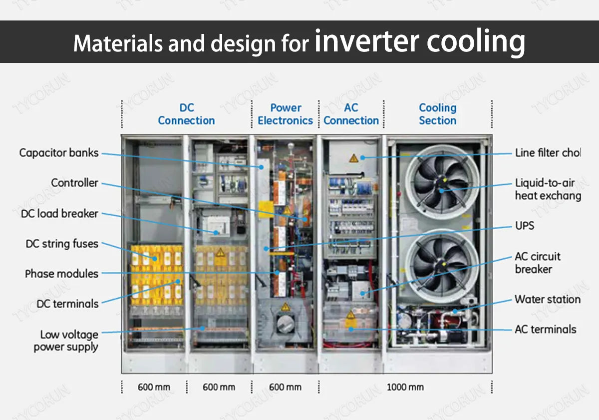
3. Inverter cooling and heat dissipation design
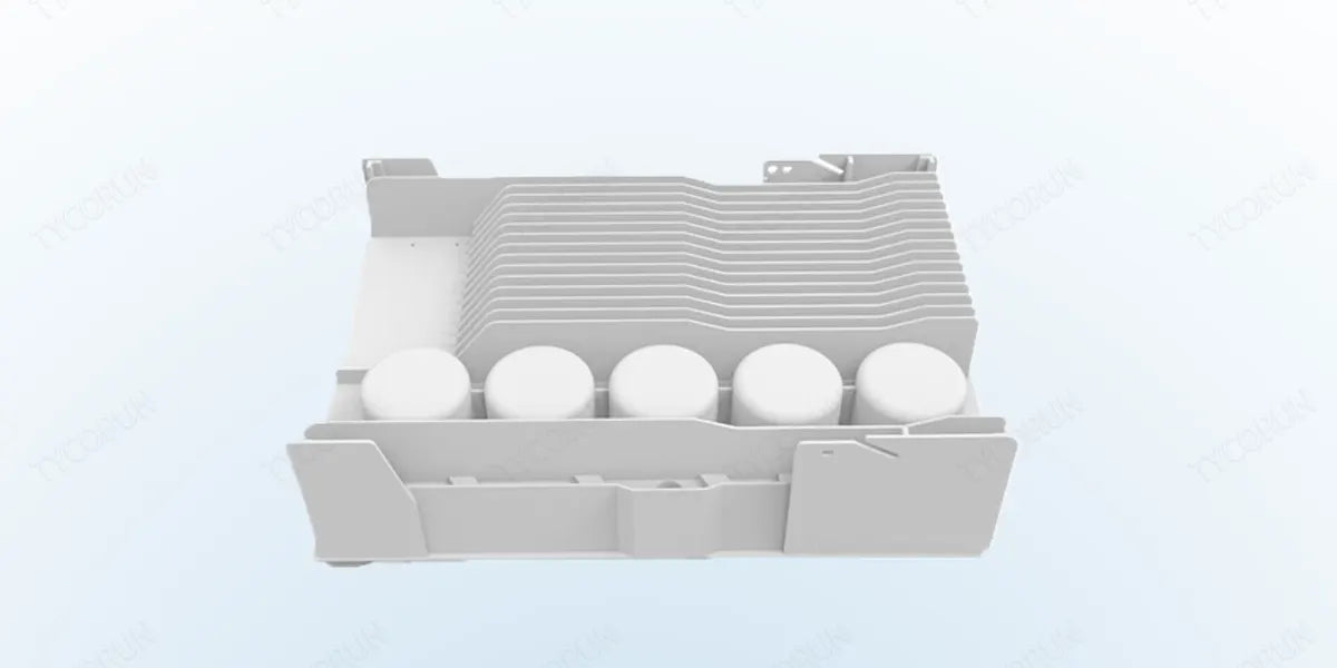
In a circuit, active components will generate heat as long as current is passed through them. The main heating components in the inverter include: switching tubes (IGBT, MOSfet), and magnetic core components (inductors, transformers), etc. Therefore, in order to ensure that the components can work at the rated temperature, the inverter cooling capacity of the system is very important.
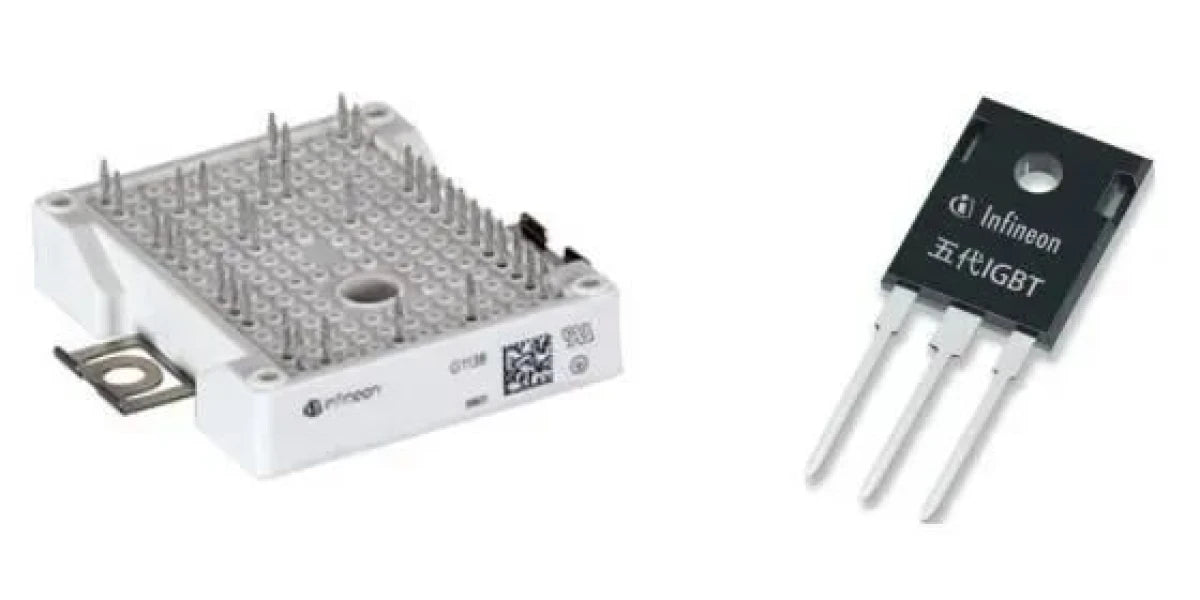
Picture: (left) power IGBT module, (right) IGBT tube

Picture: Magnetic core components
It is inevitable that the inverter will generate heat when it is working. For example, for a 5kW inverter, the general system heating power is about 1.5-2.5% of the total power of the inverter, and its heat loss is about 75-125W. Therefore, system heat dissipation and inverter cooling are very important.
For small household systems, the industry usually uses natural inverter cooling methods. To achieve excellent heat dissipation performance, the following points are recommended:
- The larger the heat dissipation area, the better the effect
For example, the heating power of a 5kW inverter is 125W. Based on the calculation that the maximum heat flux density that natural inverter cooling can bear at 60℃ is 0.05W/cm2, the inverter cooling area is at least about 0.25m2. In order to maintain the same volume and increase the surface area of the radiator, the surface of the radiator is designed with multiple heat dissipation teeth and wrinkles, which increases the contact area between the radiator and the air, which is conducive to inverter cooling.
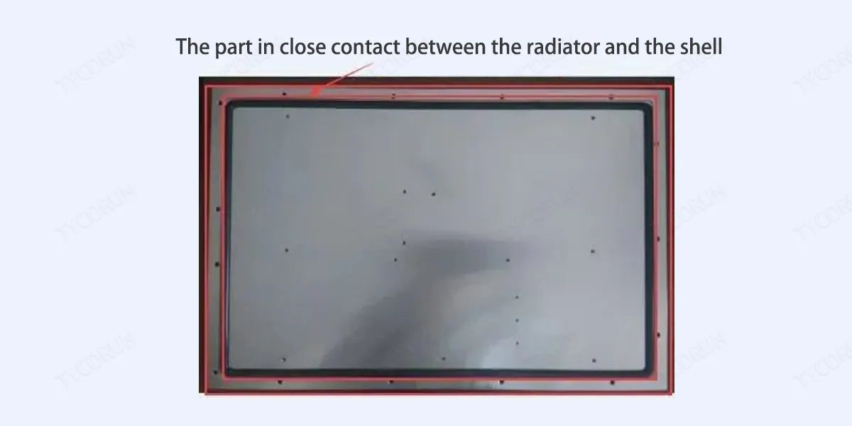
- Close joint structure of the shell and radiator
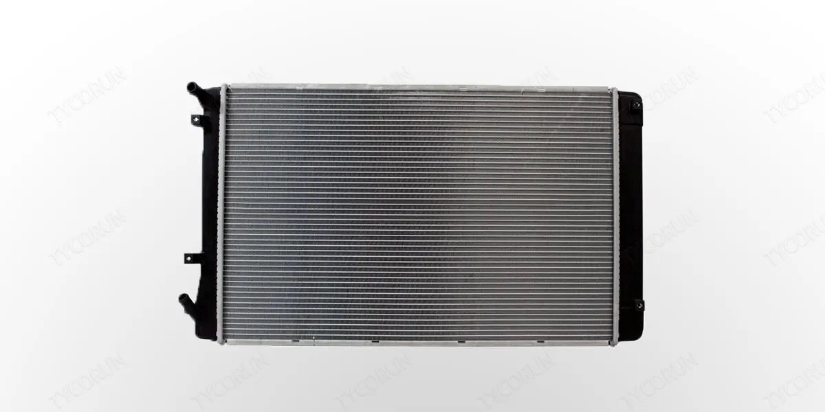
The inverter casing is made of aluminum alloy and has good thermal conductivity. As shown in the figure below, the integrated shell structure is used. The radiator and the shell are directly and tightly connected through a large area. The heat of the components can be directly transferred to the aluminum alloy shell through the radiator, forming a inverter cooling path of device → radiator → shell → external air.
In addition, the heat of the components can be conducted to the casing through the air inside the inverter, and then dissipated to the outside air through the casing. Another heat dissipation path is formed from device → internal air → shell → external air.
Using a non-integrated shell, the shell and the radiator need to be connected twice, and the contact is not tight. Therefore, only the radiator and a small part of the middle shell participate in inverter cooling, and the upper shell does not participate in inverter cooling, which greatly reduces the overall inverter cooling performance.
As we can see from the figure below, when the integrated shell structure is used, the radiator and the shell are directly and closely connected, allowing the aluminum alloy shell to participate in heat dissipation through two paths. Because more is involved in inverter cooling, the temperature of the inverter shell is relatively high.
The benefit of this phenomenon is that the good thermal conductivity of the casing transfers the internal heat of the inverter out through the casing faster, thereby reducing the internal temperature of the inverter and the temperature of the components, thus ensuring that the components and the inverter are more reliable with longer service life. For the best inverter, you can click to check battery stores near me.
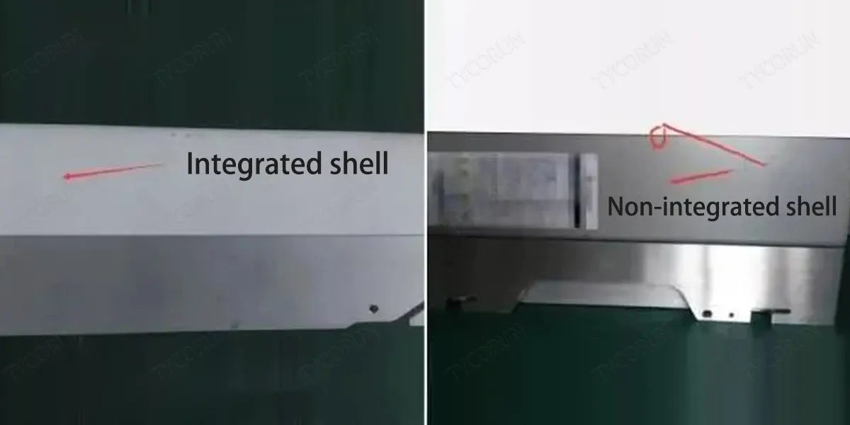
Picture: (left) integrated shell, (right) non-integrated shell
External inductor design
As shown in the figure below, the structural design with an external inductor can externally place the power inductor of the heating device to reduce the temperature inside the chassis. The inductor can efficiently dissipate heat independently.
Picture: External inductor design
4. Heat dissipation of TYCORUN inverter
TYCORUN's all series of inverters, including 3000w inverter that works with LFP battery, are made of aluminum alloy, which has a large heat dissipation area and fast inverter cooling. It also has an ultra-silent cooling system that starts the cooling fan according to the temperature.
Taking the TYCORUN 1000w inverter as an example, the cooling fan will start when the inverter load reaches 1500w, or when the internal components are greater than 45℃. For the maintenance of the inverter, inverters should be in an area where the fans are not blocked. And do not put the inverter under direct sun light or near a heating source.

(Click the picture for more information of TYCORUN inverters.)
5. Causes of heating of inverter shell
In order to lower the temperature of components better and faster, and ensure longer service life of components, the design of the integral shell and the radiator is closely contacted, making the shell an important part of the system's heat dissipation. When the inverter cooling performance is enhanced, the shell temperature will get higher, which is a normal phenomenon of the inverter operation.
Due to the need for inverter cooling and the particularity of the working environment (direct outdoor sunlight), safety standards stipulate that the inverter shell temperature cannot exceed 70℃. In summer, when the external ambient temperature is 40℃, the shell temperature is generally between 55℃ and 60℃, so people will feel hot when touching the inverter shell.
Summary
From the relationship between component temperature and lifespan, and the principle of the inverter cooling structure, the casing becomes a part of the inverter cooling device and choosing the appropriate shell material and heat dissipation design can benefit inverter cooling. Although the outer shell temperature rises and heat occurs, the temperature of the internal components of the inverter will drop even more and faster. This ensures longer service life and normal operation of components and inverters.
You can also check our Tycorun inverter products if needed: car inverter 3000w, 2000 watt pure sine wave inverter, 1000w car inverter, 500 w power inverter
Related posts: Power wheels battery, Inverter batteries near me, Best solar inverter brands


