

As an important way to alleviate the range anxiety of new energy vehicles, fast charging is one of the important ways for battery manufacturers and vehicle manufacturers to improve their power wheels battery capabilities.
The continuous iteration of fast charging technology and the accelerated application of fast charging solutions have put forward higher requirements for battery materials and are expected to bring new development opportunities to battery material manufacturers. The battery material, especially the anode material, determines the upper limit of the battery cell to a large extent.
Main content:
1. Anode determines the fast charging performance
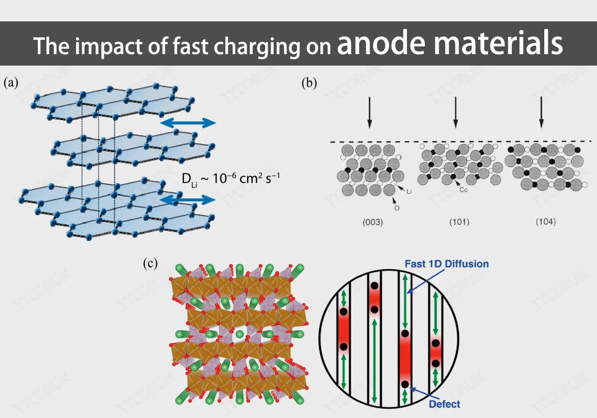
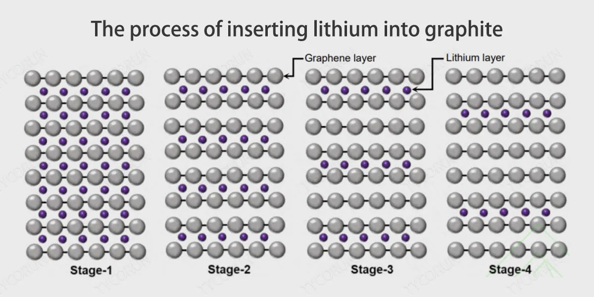
Since the graphite anode has a layered two-dimensional structure, during the charging process, the trajectory of lithium ions is to separate from the positive electrode, diffuse into the electrolyte, and finally be inserted between the graphite layers. At this time, the reaction at the anode is 6C+x〖Li〗^++xe−↔〖Li〗_x C_6.
Among them, x≤1, when x=1, the lithium ions embedded in the graphite layer are saturated, forming LiC_6, corresponding to the theoretical specific capacity of 372mAhg^(−1). Therefore, the deintercalation speed of lithium ions between graphite layers determines the fast charging performance of the battery, such as 18650 battery.
However, there are still some bottlenecks in the direct application of graphite anodes to fast-charging LFP battery:
- Due to the anisotropy of the graphite layer and the narrow spacing between the layers, lithium ions can only move parallel between the graphite layers and cannot move vertically, which reduces the diffusion coefficient of lithium ions;
- When lithium ions are embedded in the graphite layer, they enter from the edge of the layer. The longer diffusion path reduces the rate capability of the lithium-ion battery;
- The graphite layers are connected by weak Van der Waals' force, and the structure is unstable. The lithium ion embedding process will be accompanied by the embedding of solvent molecules, causing the graphite layer to peel off;
- Under fast charging conditions, the lithium insertion potential of the graphite layer will be close to the lithium deposition potential (the lithium precipitation effect mentioned earlier), thus reducing the performance of the battery.
2. Three ways to improve the multiplier performance of the anode
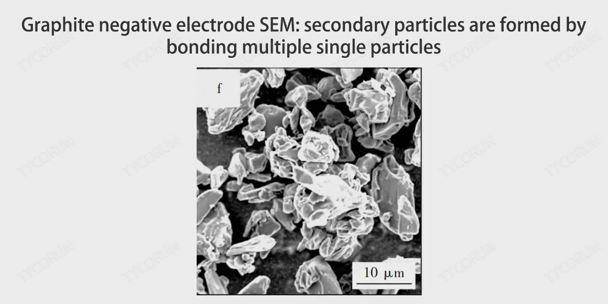
① Secondary granulation to create large particles of lithium ion space movement channel
The process of granulation is to implant the material into the ball mill under a certain temperature and pressure, and sieve. The purpose of primary granulation is to reduce the volume of anode particles, and the purpose of secondary granulation is to bond small particles into large particles. For the multiplier, the smaller the anode particle is, the larger the specific surface area of the particle is, and the channel of lithium ion migration will increase and the path will become shorter, which is more conducive to the movement of lithium ion.
In terms of capacity, the larger the anode particle, the higher the compaction density, and the higher the space utilization rate of active particles, which is more conducive to lithium storage. The secondary particles prepared by granulation can take into account the advantages of large and small particles.
|
Sample |
Particle size distribution/µm |
Tap density/g·cm-3 |
Specific surface area/㎡·g-1 |
||
|
D10 |
D50 |
D90 |
|||
|
Sample 1 |
7.9 |
17.2 |
39.1 |
1.01 |
1.88 |
|
Sample 2 |
8.9 |
22.4 |
55.5 |
1 |
2.46 |
|
Sample 3 |
9.2 |
20.8 |
42.5 |
1.04 |
2.72 |
|
Sample 4 |
41 |
8.8 |
16.4 |
0.76 |
4.4 |
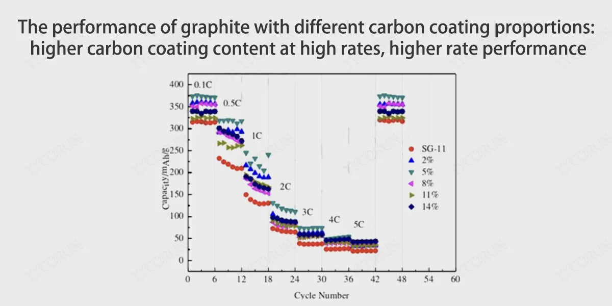
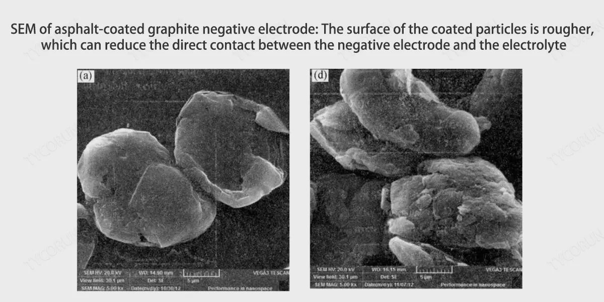
② Carbon coating creates larger graphite layer spacing and channels to inhibit graphite layer peeling
Carbon coating is to coat the carbon source (asphalt) on the surface of graphite particles through thermal decomposition to form a carbon material with a core-shell composite structure. Carbonization has three benefits for the battery anode:
- The carbon layers of amorphous carbon are disorderly arranged, the structure is isotropic, and the spacing between carbon layers is larger than the spacing between graphite layers, and lithium ions can freely move between the carbon layers.
- The surface of the amorphous carbon layer has high pores and many channels, which can guide the insertion of lithium ions into the graphite layer.
- Amorphous carbon has better compatibility with the electrolyte, which can effectively prevent the co-intercalation of macromolecule organic solvents and inhibit the peeling of the graphite layer.
③ Silicon carbon anode: improved safety + energy density
- Improve safety: During the fast charging process, the lithium potential of the graphite anode is about 0V, so it is easy to produce lithium precipitation effect. However, silicon has a higher lithium embedding platform, and the lithium potential is about 0.5V, so there is a smaller possibility of lithium precipitation on the surface, which can improve the safety of fast charging anode;
- Improve energy density: The theoretical capacity of silicon material can reach 4200 mAh/g, which is much higher than the 372 mAh/g of carbon material, and the lithium storage performance is better.
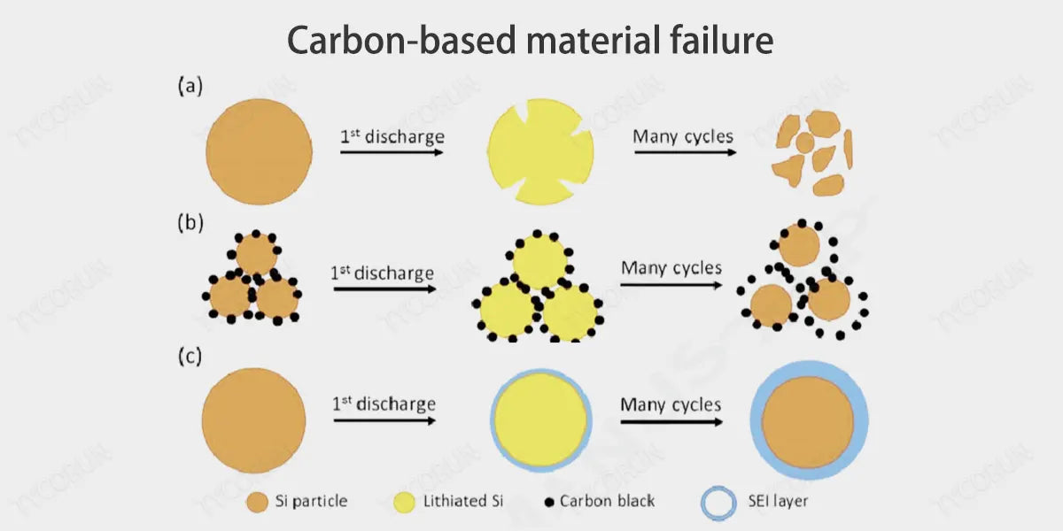
3. Current problems with silicon-based anodes
- The combination of silicon and lithium ions generates a series of alloy phases, with volume expansion up to 300%, which has a huge impact on the stability of the material. Volume expansion will produce high stress, which in turn will During charge and discharge cycles, repeated deintercalation and deintercalation of lithium ions will cause the silicon particles to pulverize, the electrochemical cycle performance will rapidly decline, and the capacity will also rapidly decay.
- Changes in silicon volume will also cause repeated formation of SEI films. , which not only reduces the Coulomb efficiency, but also increases the impedance and delays the transmission rate of lithium ions.
- Carbonaceous anode materials have small volume changes during charging and discharging, and have good cycle stability, and the carbonaceous anode materials themselves are mixed conductors of ions and electrons; in addition, silicon and carbon have similar chemical properties, and the two can be closely combined, and therefore can be used as the preferred matrix for composites with silicon.
The structure of silicon-carbon composite materials is mainly divided into: core-shell structure, yolk structure, and embedded structure, etc.
Core-shell structure:
The "core-shell" structure uniformly coats carbon materials on the silicon surface. Carbon material coating can:
- Improve the characteristics of silicon-based material semiconductors and enhance conductivity;
- As a mechanical protection support to buffer the volume expansion of silicon;
- The carbon coating acts as a separation, reducing the contact between Si and the electrolyte, reducing the occurrence of side reactions, and stabilizing the SEI layer.
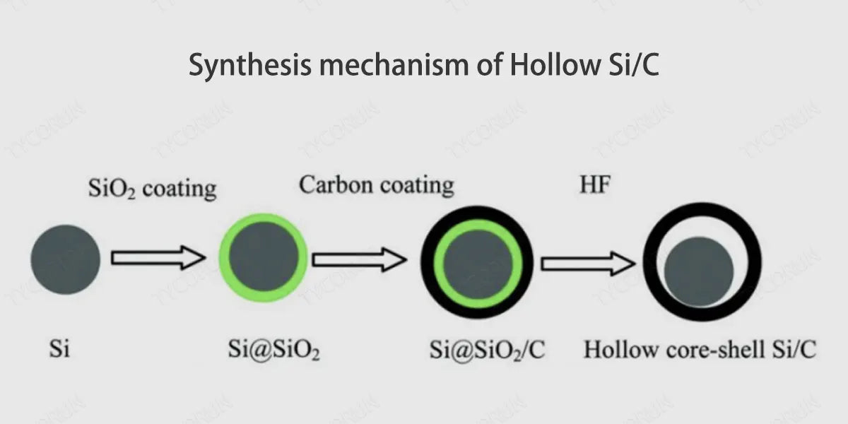
Yolk structure:
With Si as the core and the carbon layer as the shell, a cavity is introduced between Si and carbon to form a silicon-carbon anode material with an "yolk" structure. The outer carbon layer effectively separates the Si core and the electrolyte, reducing side reactions, avoiding excessive consumption of Li+, and reducing irreversible capacity loss. The cavity inside the structure effectively buffers the volume expansion of silicon and maintains the structural stability of the material.
Embedded structure:
Embedded Si/C composites refer to silicon materials being continuously embedded in a carbon matrix. Among them, carbon material serves as a buffer layer, which can greatly improve the cycle stability of the battery like 12 volt 100ah deep cycle lithium battery or 12 volt 200ah lithium battery. By continuously embedding Si into the carbon substrate, the resulting sandwich structure can adapt to its large volume changes, and this mechanical support enables uniform mechanical stress during expansion.
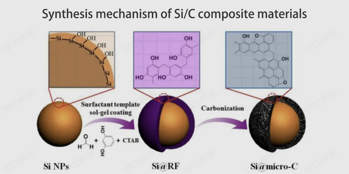
4. Preparation scheme of silicon carbon anode
Current preparation options for silicon carbon anodes include: mechanical ball milling, hydrothermal, and chemical vapor deposition.
- Mechanical ball milling:
The mechanical ball milling method is to use a ball mill to grind the mixture with suitable silicon sources and carbon sources. After completion, a tube furnace is used for sintering and annealing. During ball milling, the ball-to-material ratio, solvent, grinding time, etc. will all affect the final product. The ball milling method is used to achieve uniform dispersion of SiOx/C and graphite, which helps to mitigate the volume changes of SiOx and Si nanoparticles.
- Hydrothermal:
The hydrothermal method refers to a preparation method in which a suitable solvent is dissolved and recrystallized in a closed container. Nanoparticles prepared by the hydrothermal method rarely agglomerate, and each silicon particle is well wrapped in amorphous carbon. Under the hydrothermal method, SiOx will be formed between the carbon shell and the silicon core, making the bond between the core and the shell stronger, thereby improving cycle stability.
- Chemical vapor deposition:
Chemical vapor deposition method (CVD) refers to a method that uses appropriate chemical gases or vapors to reactively deposit coatings or nanomaterials on the surface of graphite microsphere composite materials. Silicon-carbon anodes prepared by CVD are generally divided into two structures. One is a structure in which carbon wraps silicon formed by using resin material as a precursor, and the other is a structure in which nano-silicon is embedded in a carbon matrix.
The silicon-carbon anode material synthesized by CVD reaction has good cycle stability. According to data, the silicon carbon anode prepared by the porous carbon CVD method can reach a high capacity of more than 1530mAh/g, and the material has a high first efficiency (more than 91%) and excellent cycle performance (500 cycle retention rate 93%).
Related posts: Cathode and anode, Lawn mower battery, Golf cart battery


