


The layout of substation mainly includes the overall substation layout and the layout of high-voltage distribution room, low-voltage distribution room, transformer room, control room, high-voltage capacitor room, duty room and auxiliary rooms. Today we will introduce to you how to arrange each area of substation layout and the specific requirements.
Main content:
1. Requirements for substation layout
① Ensure safe operation and convenient operation, maintenance, inspection and testing.
② Make full use of natural lighting and natural ventilation. The transformer room and capacitor room should avoid sunlight exposure as possible, and the control room should face south (the distribution panel and table should face south).
③ The substation layout should be compact and reasonable, and the entrance and exit cables of transformers, buildings and rooms should be convenient. For example, the location of the high-voltage distribution room should be convenient for incoming and outgoing lines, the low-voltage distribution room should be as close as possible to the transformer, and the high-voltage capacitor room should be connected to the high-voltage distribution room, etc.
④ 10(6)KV substation layout should be arranged in a single floor. When a two-floor substation layout is adopted, the transformer should be located on the bottom floor, and the power distribution room on the second floor should have lifting holes and a lifting platform.
⑤ For substation layout, the location of the control room, duty room and auxiliary room should be convenient for the work and management of operating personnel.
⑥ When the same substation layout supplies power to the primary load, fireproof partitions with door openings should be installed at the busbar sections. The two cables supplying primary load power should not pass through the same cable trench; when they cannot be separated, the two cables in the cable trench should be flame-retardant cables and should be laid on brackets on both sides of the cable trench respectively.
⑦ The substation layout should not have pipes and lines that are not related to it.
⑧ Transformer rooms, high and low voltage distribution rooms, and capacitor rooms, etc. should all have measures to prevent rain, snow, and small animals from entering the room through lighting windows, ventilation windows, doors, cable trenches, cable protection tubes, etc.
⑨ Appropriate spare intervals and room for expansion should be left in the high and low voltage power distribution system and transformer rooms. When we plan for substation layout, there should be an appropriate number of spare positions for switch cabinets (panels) in high and low voltage power distribution rooms, and the outline of the transformer should be considered one level larger than its capacity.
⑩ Each three-phase transformer with an oil capacity of 100kg and above in an indoor substation should be located in a separate transformer room.
⑪ The floors of high and low voltage power distribution rooms, control rooms, duty rooms, etc. should be 150 to 300 mm higher than the outdoor ground. When attached to a building, it can be flush with the floor of the building.
⑫ The doors of high and low voltage power distribution rooms, transformer rooms, and capacitor rooms should open outwards. When there is a door between adjacent power distribution rooms, the door should be opened in both directions or in the low-voltage direction.
⑬ Doors and windows that are frequently opened in each room should not be directly facing adjacent places with corrosive gas, dust and noise.
2. Overall substation layout
Layout of high voltage distribution room
① The high-voltage power distribution room should be equipped with a natural lighting window that cannot be opened, and a wire mesh should be installed outside the window to prevent the entry of rain, snow, small animals and sand and dust. For proper substation layout, the window sill should not be less than 1.8m higher than the outdoor floor, and windows should not be opened towards the street side for the best substation layout.
② High-voltage power distribution devices with flammable oil should be installed in a separate high-voltage power distribution room; when the number of 10(6)kV high voltage switchgear is 6 or less, they can be installed in the same room as the low-voltage power distribution panel.
③ For high and low voltage power distribution devices arranged in single rows in the same power distribution room, when there are exposed live conductors on the top of the high-voltage switch cabinet or low-voltage power distribution panel. For proper substation layout, the net distance between the two should not be less than 2m; but when the protection level of the top shells of the two meets IP2X, they can be placed close for substation layout.
The substation layout of the indoor high voltage distribution unit can be referred to the picture below:
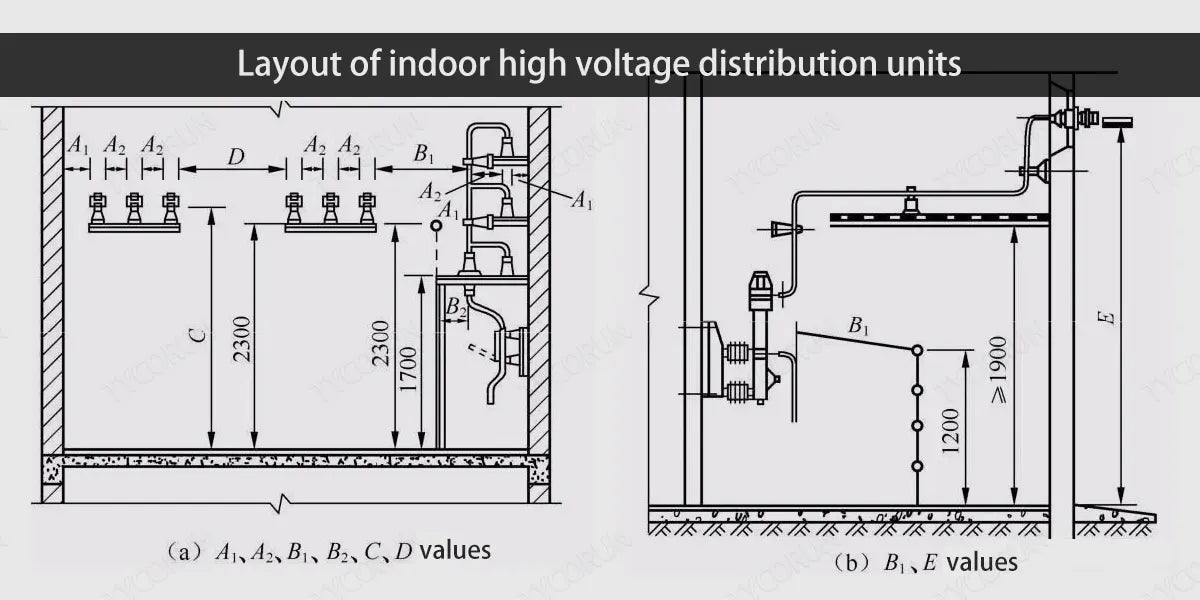
- When the lowest insulation part of the casing and insulator of electrical equipment is less than 2.30m from the ground (floor) surface, a fixed fence should be installed for proper substation layout.
- The net distance between the upward extension line of the fence and the live part above the fence at a distance of 2.30m from the ground (floor) surface should not be less than the A1 value in table below, for proper substation layout.
Minimum safety net distance for indoor high voltage distribution units (unit: mm)
|
Item |
Rated voltage (KV) |
|
|
6 |
10 |
|
|
From live part to earthed part (A1) |
100 |
125 |
|
Between live parts of different phases |
100 |
125 |
|
1. Live part to fence (B1) 2. Between uncovered fenced live parts crossing different simultaneous outages |
850 |
875 |
|
Between energised parts and mesh fences (B2) |
200 |
225 |
|
Unshielded bare conductor to ground (floor) surface (C) |
2500 |
2500 |
|
Horizontal net distance (D) between unshielded bare conductors without simultaneous power outages for maintenance |
1900 |
1925 |
- Exposed conductive parts located above the ground (floor) surface, whose dimensions are less than the value of C, should be isolated by a barrier, and the height of the passable part below the barrier should not be less than 1.90m for proper substation layout.
The width (net distance) of various channels in the high-voltage distribution room should not be less than the values specified in the table below. (unit: m)
|
Switch cabinet layout |
Maintenance channel behind the cabinet |
Operating channel |
Channel leading to explosion-proof compartment |
||
|
Fixed type |
Handcart type |
||||
|
Single row layout |
0.8 |
1.5 |
Single vehicle length+1.20 |
1.2 |
|
|
Switch cabinets on both sides |
Face to face |
0.8 |
2.0 |
Double vehicle length+0.90 |
1.2 |
|
Back to back |
1.0 |
1.5 |
Single vehicle length+1.20 |
||
- The net height of high-voltage power distribution room is generally 4.2~4.5m. The distance between the high-voltage power distribution device and the roof (except beams) is 0.80m.
- There should be no exposed lighting or power lines crossing the exposed live parts of indoor high-voltage power distribution devices (except for power distribution devices with IP4X protection grade enclosures on the top).
- When the length of the high-voltage distribution room exceeds 7m, two doors should be opened and arranged at both ends. The height of the transport door of the GC-1A(F) high-voltage switch cabinet is 2.5~2.8m and the width is 1.5m.
- When the power line enters from the back of the cabinet, and an isolation switch and its manual operating mechanism need to be installed on the wall directly behind the cabinet, the clear width of the passage behind the cabinet should not be less than 1.50m for proper substation layout; when the protection level on the back of the cabinet is IP2X , it can be reduced to 1.30m.
Layout of low voltage distribution room
① When the length of low-voltage power distribution panels arranged in rows exceeds 6m, the passage behind the distribution panel should have two exits leading to this room or other rooms, and should be arranged at both ends of the passage. When the distance between two exits exceeds 15m, additional exits should be added in between.
② Low-voltage power distribution panels are generally not installed against the wall. The distance behind the panel is 1 to 1.2m from the wall. If there are channels at both ends of the panel, there should be protective plates.
③ When the length of the low-voltage distribution room exceeds 7m, the doors should be opened at both ends.
④ When the low-voltage power distribution room doubles as the duty room, the front face of the power distribution panel shall not be less than 3m for proper substation layout.
⑤ The height of the low-voltage power distribution room: 3.5~4m when adjacent to the transformer; when the cable enters, the height shall not be less than 3m.
⑥ For two sections of busbars in the same power distribution room, if any section of the busbar has a primary load, fireproof partition measures should be taken at the busbar section.
⑦ The height of the exposed live body above the passage of the low-voltage distribution room from the ground should not be lower than the following values: 2.50m in the passage in front of the distribution panel. The height can be reduced after adding a protective net, but the minimum height of the protective net is 2.20m; behind the distribution panel, the height inside the passage is 2.30m, otherwise it should be shielded, and the height after shielding should not be less than 1.90m for the best substation layout.
⑧ The low-voltage capacitor device can be installed in the low-voltage distribution room. When the total capacity of the capacitor is large, it should be installed in a separate room.
Layout of control room
① The main equipment installed in the control room includes control panel, signal screen, power screen, etc. Except for large and medium-sized factory substations, there is no need to set up a separate control room in substation layout of general property power supply such as home solar power system.
② The control room is generally connected to the 6-10kV high-voltage power distribution room. The relay protection and measuring instruments of the 6-10kV high-voltage distribution device are generally located on the corresponding switch cabinet and operated locally; the signaling device is located in the duty room, and can also be operated centrally in the control room when necessary.
③ The substation layout of the control room screens must be easy to install and debug. The substation layout arrangement scheme depends on the number of screens, and a straight-line or L-shaped arrangement is often used. Generally, the control panel and signal panel are arranged on the front, and the power panel and all electric panels are arranged on the side or both sides of the front.
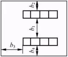
The distances between screens and passages in the control room are shown in the table below. Distance between screens and passages in the control room (unit: mm)
|
Diagram |
Symbol |
Name |
General value |
Minimum value |
|
|
b1 |
Screen front - Screen back |
1300~1500 |
1200 |
|
b2 |
Screen back - Wall |
1000~1200 |
800 |
|
|
b3 |
Screen edge - Wall |
1000~1200 |
800 |
|
|
b4 |
Main screen front - Wall |
1300 |
/ |
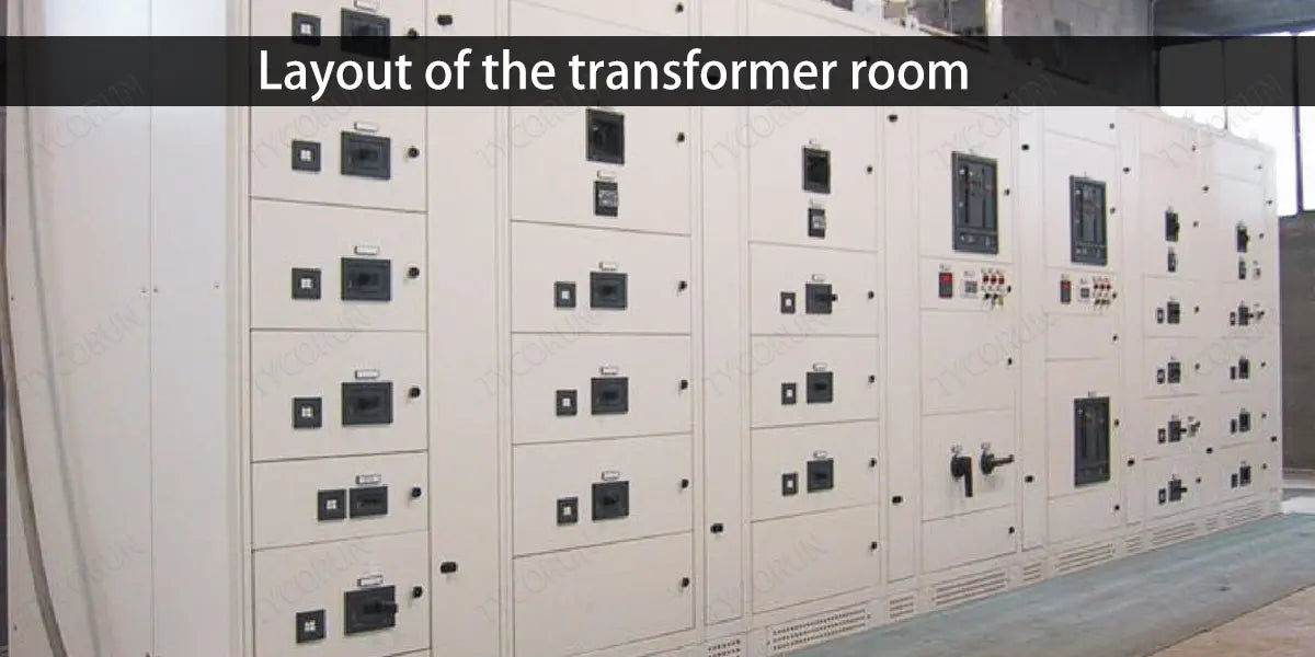
Layout of the transformer room
The structure and layout of the transformer room depends on factors such as the type, capacity, placement of the converter or inverter (such as 2000w inverter or 3000w inverter), the main electrical wiring scheme, the way and direction of the incoming and outgoing wires, and should consider safety and convenience of operation and maintenance, as well as ventilation, lighting, fire protection, recent development, etc., for substation layout.
① The protection level of the metal mesh shield of the dry-type transformer shall not be lower than IP1X, and the height of the shield shall not be lower than 1.70m.
② For indoor oil-immersed transformers for on-site maintenance, the indoor height can be determined by adding 0.70m to the minimum height required for the hanging core, and the width can be determined by adding 0.80 to 1.0m to both sides of the transformer. If the transformer room is equipped with high-voltage load switches, isolating switches, fuses, etc., the width of the transformer room should be increased accordingly.
③ The substation layout of oil-immersed transformers and other oil-filled electrical appliances should consider the convenience and safety of observing the oil level and oil temperature when electrified, and make it easy to draw oil samples.
④ Natural ventilation should be used in the transformer room. The exhaust air temperature in summer should not be higher than 45℃, and the temperature difference between the inlet air and exhaust air should not be greater than 15℃. When the transformer is arranged indoors, it should be arranged overhead above the ground, and blinds should be opened from the floor to the bottom of the transformer to facilitate ventilation and heat dissipation (the floor of a transformer room with a capacity of 630kVA and below generally does not need to be raised). Ventilation windows should be made of non-combustible materials.
⑤ The fire resistance grade of the flammable oil-immersed transformer room should be Level 1. The fire resistance grade of the transformer room, high-voltage distribution room and high-voltage capacitor room with non-combustible (or refractory) media should not be lower than Level 2. The fire resistance level of the low-voltage distribution room and The fire resistance rating of the low-voltage capacitor room shall not be lower than Level 3.
Under any of the following circumstances, the door of the transformer room should be a Class-A fire door:
- The transformer room is located in the main high-rise building;
- There are flammable items near the transformer room or lead to the garage;
- The transformer is located on the second floor or higher of the building;
- The transformer is located in the basement or there is a basement below;
- The door from the transformer room to the high and low voltage distribution rooms;
- Doors between transformer rooms;
- The transformer room is located in the workshop or station building.
⑥ When the following conditions occur, the oil-immersed transformer room should be equipped with an oil retaining facility with a capacity of 100% of the transformer oil (a facility that prevents burning oil from spilling) or a facility that can drain the oil to other safe places:
- There are places where flammable materials accumulate near the transformer room;
- There is a basement below the transformer room;
- The transformer room is located in the main civil building.
- The combustible oil-immersed transformer room in the attached substation and the substation in the workshop should be equipped with an oil storage tank with a capacity of 100% of the transformer oil (the oil will not be delayed by external burned substances after it flows in) facilities and can drain the oil to a safe place for substation layout.
- In attached substations, open-air or semi-open-air substations, transformers with an oil capacity of 1000kg and above should be equipped with oil retaining facilities with a capacity of 100% of the oil capacity.
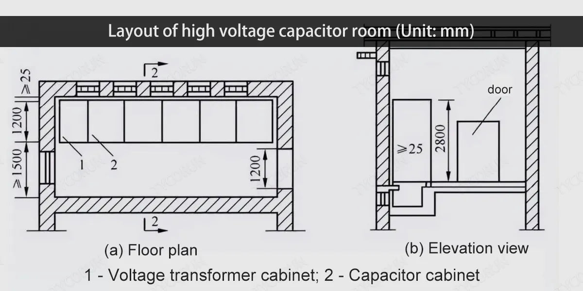
Layout of high voltage capacitor room
- In order to improve the power factor, indoor high-voltage capacitor complete sets are installed on the 10kV bus side of large and medium-sized substation layout.
- High-voltage capacitor devices (capacitor cabinets) should be installed in a separate room. When the capacity of the capacitor bank is small, it can also be installed in the high-voltage distribution room, but the distance from the high-voltage distribution device should not be less than 1.5m. The high-voltage capacitor room should have good natural ventilation for proper substation layout.
- The effective area of the ventilation window can be calculated based on the inlet air temperature, requiring a lower air inlet area of 0.1~0.3m2 and an upper air outlet area of 0.2~0.4m2 per kVA. The bottom of the lower capacitor should not be less than 0.2m from the ground, the bottom of the upper capacitor should not be more than 2.5m from the ground, and the clear distance from the top of the capacitor device to the roof should not be less than 1.0m for proper substation layout. The layout of high-voltage capacitors should not exceed 3 floors.
- The clear distance between capacitor shells (wide surface) should not be less than 0.1m, and the distance between capacitor rows should not be less than 0.2m. When the capacitor room is connected to the high and low voltage distribution rooms, there should be a fire partition wall in between. When the indoor length exceeds 7m, the doors should be opened at both sides.
- When a complete set of capacitor cabinets is arranged in a single row, the distance between the front of the cabinet and the wall should not be less than 1.5m; when a complete set of capacitor cabinets is arranged in a double row, the distance between the cabinets should not be less than 2.0m.
Layout of duty room
For a manned substation layout, a separate duty room (which can also serve as a control room) should be set up. A manned independent substation layout should be equipped with restrooms and water and sewer facilities.
When there is a low-voltage distribution room, the duty room can be combined with the low-voltage distribution room. In this case, the distance from the low-voltage distribution device to the wall on the side or end where the duty personnel often work should not be less than 3m.
The structural type and layout of the duty room should be conducive to operation and maintenance, and should be close to the high and low voltage distribution rooms. The high-voltage power distribution room and the duty room should be connected directly or through the corridor. The duty room should have a door that leads directly to the outdoors or the corridor.
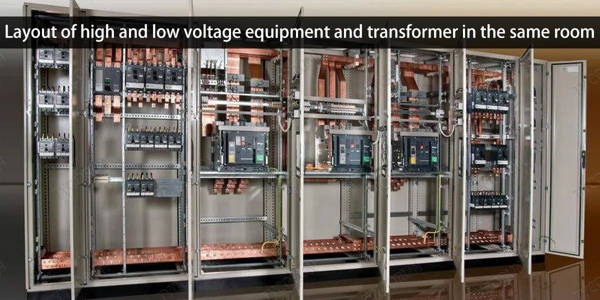
Layout of high and low voltage equipment and transformer in the same room
In order to save the floor space, after technical and economic comparison and taking corresponding measures, the high-voltage, substation, and low-voltage equipment of the substation layout can be arranged in the same room without any separation. This not only makes investment economical, but also facilitates operation, maintenance and management, but safety must be ensured when it comes to substation layout.
① All electrical equipment (including capacitors) should be non-flammable.
② The exposed live parts of transformers and other equipment must be isolated by fences.
③ The distance between each equipment and the distance between the equipment and the building roof, walls, doors and windows, etc. should comply with relevant national regulations and the technical requirements of related electrical products.
④ The duty room should be set up separately.
⑤ There should be two or more exits, at least one of which can be directly connected to the outside.
⑥ A fixed automatic alarm system and automatic fire extinguishing system should be installed.
Related posts: global top 10 best solar inverter brands, inverter buying guide, home inverter near me


