

High voltage switchgear is an important part of the manufacturing industry of power transmission and power conversion system, and occupies an important position in the entire power industry. This article will introduce to you what a high voltage switchgear is and how to judge and deal with the faults in a high voltage switchgear.
Main content:
- What is a high voltage switchgear
- Structure of high voltage switchgear
- Classification of high voltage switchgear
- Protection functions of high voltage switchgear
- Power transmission procedures of high voltage switchgear
- Power failure operation of high voltage switchgear
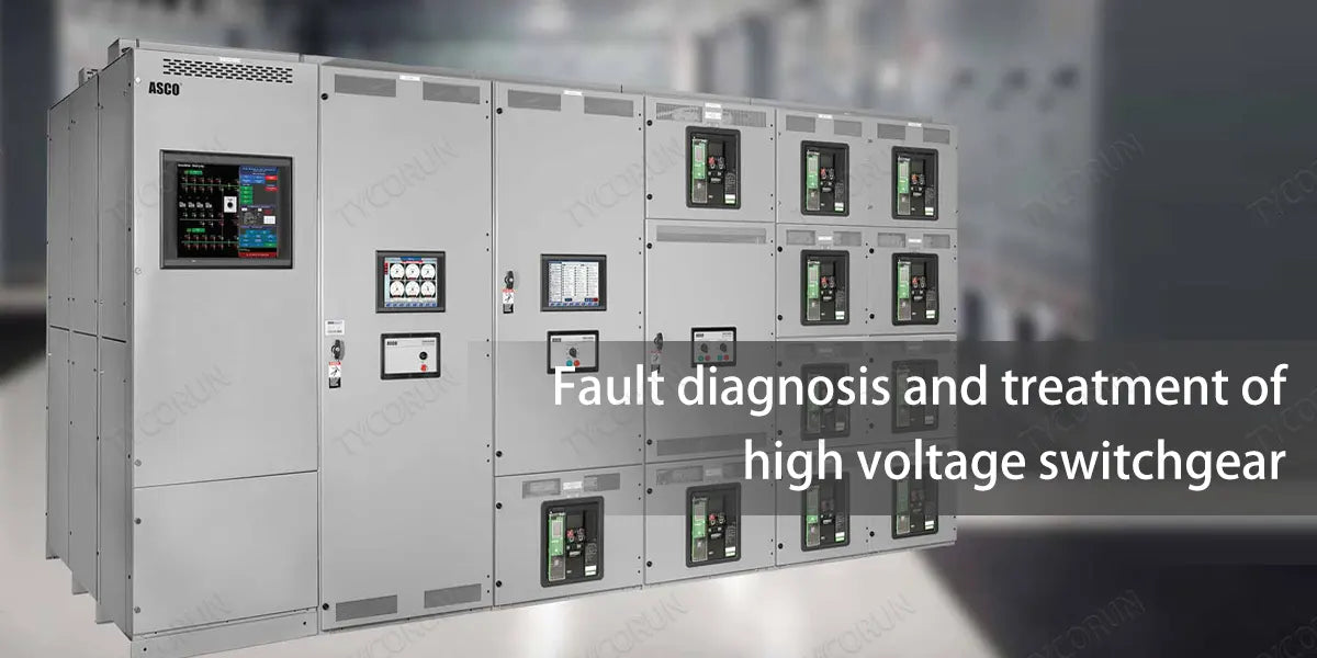
- Fault diagnosis and treatment of high voltage switchgear
1. What is a high voltage switchgear
High voltage switchgear is an electrical product that used in power generation, transmission, distribution, power conversion (just like the function of 2000w inverter or 3000w inverter) and consumption in power systems like home solar power system to perform switching, control or protection functions. The voltage level is between 3.6kV and 550kV. They mainly include high-voltage circuit breakers and high-voltage isolation.
Functions: The high voltage switchgear has functions such as overhead incoming and outgoing lines, cable incoming and outgoing lines, and busbar contact.
Applications: Suitable for various places such as power plants, substations, power system substations, petrochemical industry, metallurgical steel rolling, light industry and textile, factories and mines, residential areas, high buildings, etc.

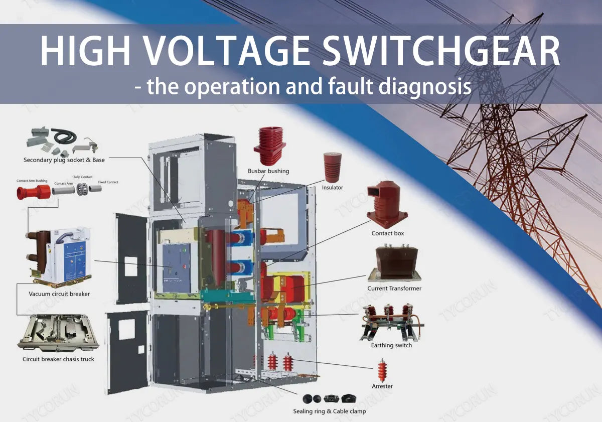
2. Structure of high voltage switchgear
It is mainly composed of the cabinet, high-voltage vacuum circuit breaker, energy storage mechanism, trolley, grounding knife switch and comprehensive protector.
① Cabinet
It is pressed and formed with iron plates and has a closed structure. It is equipped with an instrument room, a trolley room, a cable room, a busbar room, etc., and each room is isolated by iron plates. The instrument room is equipped with comprehensive protectors, ammeters, and voltmeters, etc.
The trolley room is equipped with trolleys and high-voltage vacuum circuit breakers; the busbar room is equipped with three-phase busbars; and the cable room is used to connect power cables to the outside.
② High voltage vacuum circuit breaker
The main contact of the high-voltage vacuum circuit breaker is installed in a closed vacuum chamber. When the contact is turned on and off, the arc has no gas to support combustion, so it will not burn out and is durable. At the same time, the base is made of insulating material to improve the insulation property of the vacuum switch, so it is called high voltage vacuum circuit breaker.
③ Trolley mechanism
Install the high-voltage vacuum circuit breaker on the trolley and move with the trolley. When you shake the handle clockwise, the trolley enters the cabinet and carries the vacuum circuit breaker into the high voltage circuit. When the handle is cranked counterclockwise, the trolley exits the cabinet and drives the vacuum circuit breaker to draw out the high voltage circuit.
④ Energy storage mechanism
A small motor drives the spring to store energy, and the spring releases kinetic energy to close the vacuum circuit breaker.
⑤ Grounding knife switch
It is a kind of knife switch for safety interlocking, when the grounding knife switch is closed, the high voltage switchgear door can be opened, otherwise, the high voltage switchgear door can't be opened when the grounding knife switch is not closed, which plays the role of safety interlocking protection.
⑥ Comprehensive protector
It is a kind of microcomputer protector, which is composed of microprocessor, display, keypad and peripheral circuit. It is used to replace the original relay protection circuit of over-current, over-voltage and time.
Input signals: current transformer, voltage transformer, zero-sequence current transformer and switching signals, etc.; the keyboard can be used to set the current value, voltage value, quick-break time, start-up time and other data; the display can show the real-time data and participate in the control and execution of the protection action.
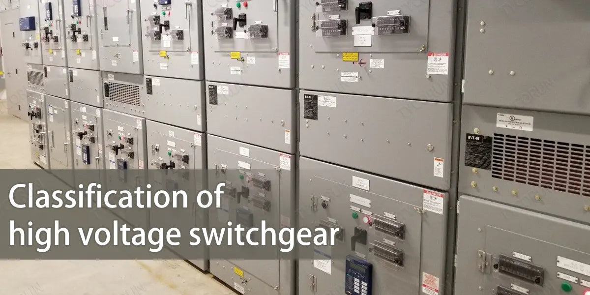
3. Classification of high voltage switchgear
- According to the main wiring form of the switchgear cabinet, it can be divided into bridge wiring switchgear cabinet, single bus switchgear cabinet, double bus switchgear cabinet, single bus sectional switchgear cabinet, double bus with bypass bus switchgear cabinet and single bus sectional with bypass bus switchgear cabinet.
- According to the installation mode of circuit breaker, it can be divided into fixed switchgear cabinet and move-open (trolley type) switchgear cabinet.
- According to the cabinet structure, it can be divided into metal-enclosed interval switchgear cabinet, metal-enclosed armoured switchgear cabinet and metal-enclosed box-type fixed switchgear cabinet.
- According to the circuit breaker handcart installation location of the way, can be divided into floor-standing switchgear cabinet and in the middle of the switchgear cabinet.
- According to the different insulation medium inside the switchgear cabinet, it can be divided into air insulated switchgear cabinet and SF6 gas insulated switchgear cabinet.
4. Protection functions of high voltage switchgear
- Prevent closing with load: After the vacuum circuit breaker trolley inside the high voltage switchgear is closed in the test position, the trolley circuit breaker cannot enter the working position.
- Prevent closing with grounding line: When the grounding knife in the high voltage switchgear cabinet is in the closing position, the trolley circuit breaker cannot enter the closing position.
- Prevent from mistakenly entering the charged interval: When the vacuum circuit breaker inside the high voltage switchgear is working in the closed position, the back door of the panel cabinet is locked with the cabinet door by the machinery on the grounding knife.
- Prevent from closing the grounding line with electricity: The vacuum circuit breaker in the high voltage switchgear is closed when working, and the grounding knife cannot be put into use.
- Prevent from pulling the knife with load: High voltage switchgear within the vacuum circuit breaker in the work of closing operation, can not be withdrawn from the trolley circuit breaker working position.
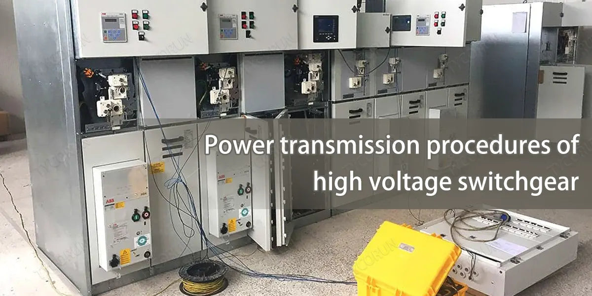
5. Power transmission procedures of high voltage switchgear
- Close all the back doors and cover plates, and lock them, and close the back door only when the grounding switch is in the closed position.
- Insert the grounding switch operating handle into the hexagonal hole on the lower right side of the middle door and rotate it counterclockwise so that the grounding switch is in the breaking position, and the interlocking plate at the operating hole automatically pops back to cover the operating hole, and the lower door of the cabinet is closed and locked.
- Push up the service trolley so that it is positioned, push the trolley into the cabinet so that it is positioned in the isolation position, manually insert the secondary plug and close the door of the handcart room.
- Insert the circuit breaker handcart crank into the crank socket, turn the crank clockwise for about 20 turns, if the crank is obviously blocked and accompanied by a clicking sound when the crank is removed, it means that the handcart is in the working position, the secondary plug is locked, the circuit breaker handcart main circuit is connected to view the relevant signals.
- Close meter board, split transfer switch to make the circuit breaker to close the power supply, at the same time the green light on the instrument panel extinguished, and the red light is on, it means the closing is successful.
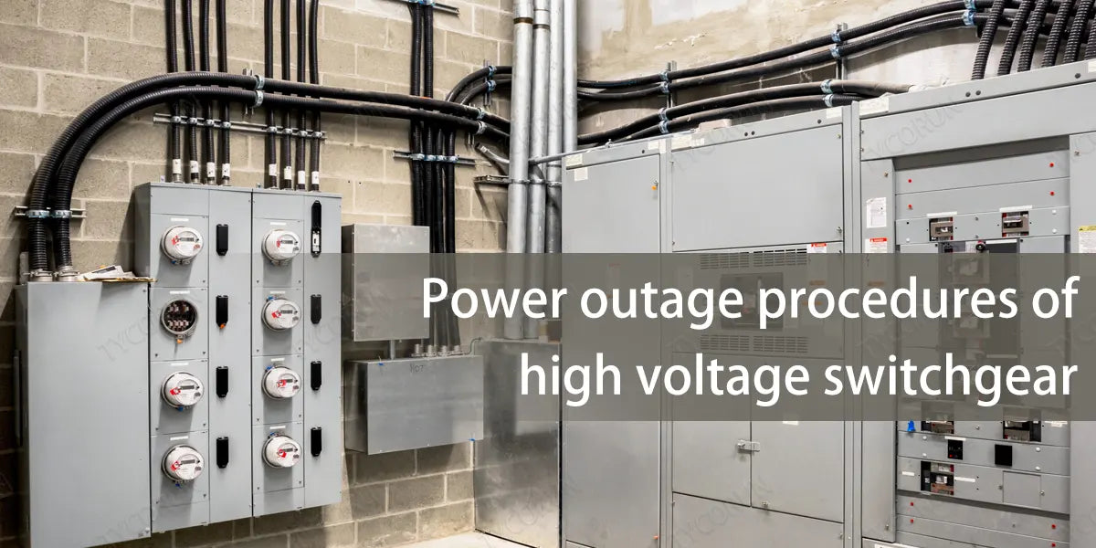
6. Power failure operation of high voltage switchgear
- Close the operating dashboard and the tap changeover switch will put the circuit breaker on tap hold, while the red light on the dashboard goes out and the green light comes on, indicating a successful tap.
- Insert the circuit breaker handcart crank into the crank socket, turn the crank clockwise for about 20 turns, if the crank is obviously blocked and with a clicking sound when the crank is removed, it means the handcart is in the test position. Lift the secondary plug locking, open the handcart room door, manually disengage from the secondary plug, and the handcart will be disconnected from the main circuit.
- Push on the service trolley so that it is locked, pull the hand trolley to the service trolley.
- Observe the charged monitor or check the electricity, if it is not charged, you can continue the operation.
- Insert the grounding switch operating handle into the hexagonal hole on the lower right side of the middle door and rotate it clockwise so that the grounding switch is in the closed position, and after determining that the grounding switch has been closed, open the lower door of the cabinet so that the maintenance personnel can enter the maintenance and overhaul.
7. Fault diagnosis and treatment of high voltage switchgear
- Protective action:
Before the switch is fed, the line has a fault protection circuit to make the anti-tripping relay work. The switch trips immediately after closing. Even if the transfer switch is still in the closed position, the switch will not be closed again for continuous jumping.
- Protection against faults:
High voltage swithgears are generally set up with the five defence functions mentioned above, the requirements of the switch is not in the operating position or test position can not be closed. That is, if the position switch is not closed, the electric switch can not be closed. This fault is often encountered in the closing process. At this time, the running position light or test position light are not on.
Move the switch trolley slightly so that the limit switch can be closed to send power. If the limit switch offset distance is too large, it should be adjusted. In JYN type high voltage switchgear, if the position switch can not be moved outward, you can add a V-type piece to ensure that the limit switch is reliably closed.
- Electrical interlocking faults:
High voltage switchgear systems will set up some electrical interlocking for the sake of reliable operation of the system. For example, in the two-way power supply into the single busbar segmentation system, the requirements of the two-way into the high voltage switchgear and the main cabinet of the three switches can only close two. If all three are closed there will be a danger of reverse power feed.
The interlocking circuits of the busbar are connected in series and then in parallel with one normally open and one normally closed of the two incoming cabinets respectively. This will ensure that the main cabinet in the two-way feeder cabinet can only send power when there is one closed and the other one is opened.
When the high voltage switchgear can not be closed electrically, the first thing to consider is whether there is an electrical chain, you should not close it manually. Electrical chain failure is generally caused by improper operation, which can not meet the closing requirements. For example, although the main feeder cabinet is a one opened and one closed, the trolley is pulled out of the branch cabinet, the plug is not plugged in. If the interlocking circuit fails, you can use a multimeter to check the faulty part.
- Open-circuit failure of control circuit:
In the control circuit, control switch damage, and line disconnection,etc. will cause that the closing coil can not get power. At this time, the closing coil has no action sound, and measure no voltage across the coil. Check this by checking the open circuit point with a multimeter.
- Closing coil failure:
The closing coil burned is a short-circuit failure. At this time there is a strange smell, smoke, and insurance fuse short. The closing coil is designed to work for a short period of time, the power time can not be too long. After the failure occurs, timely action should be taken to find the cause, and you should not repeatedly close it. Especially CD-type electromagnetic operating mechanism of the closing coil, due to the larger current through, the multiple closing will easily cause burning.
The method of trial power supply is often used when troubleshooting the failure of the high voltage switchgear to close. This method can eliminate line faults (except transformer temperature and gas faults), electrical chain faults, and limit switch faults. The fault location can basically be determined to be inside the trolley.
Therefore, for instant treatment, you can use the test position to test the power supply and replace the spare trolley for power transmission. This can reduce the power outage time, which is important for UPS power supply.
Related posts: UPS vs inverter, wind energy conversion system, top 5 PV module companies in India


