

With the rapid development of science and technology, the electrical level of many countries and regions is gradually improving, and the scope of application is becoming wider and wider, such as home solar power system. Especially in construction electrical engineering, the installation of electrical systems has a great impact on the progress of the project and the safety of the project.
Therefore, how to install and debug a low voltage power distribution system is an important part of current construction electrical engineering. So what does a low voltage power distribution system consist of? What are the main equipment? What are the functions of each part? This article will introduce it to you in detail.
Main content:
1. Composition of low voltage power distribution system
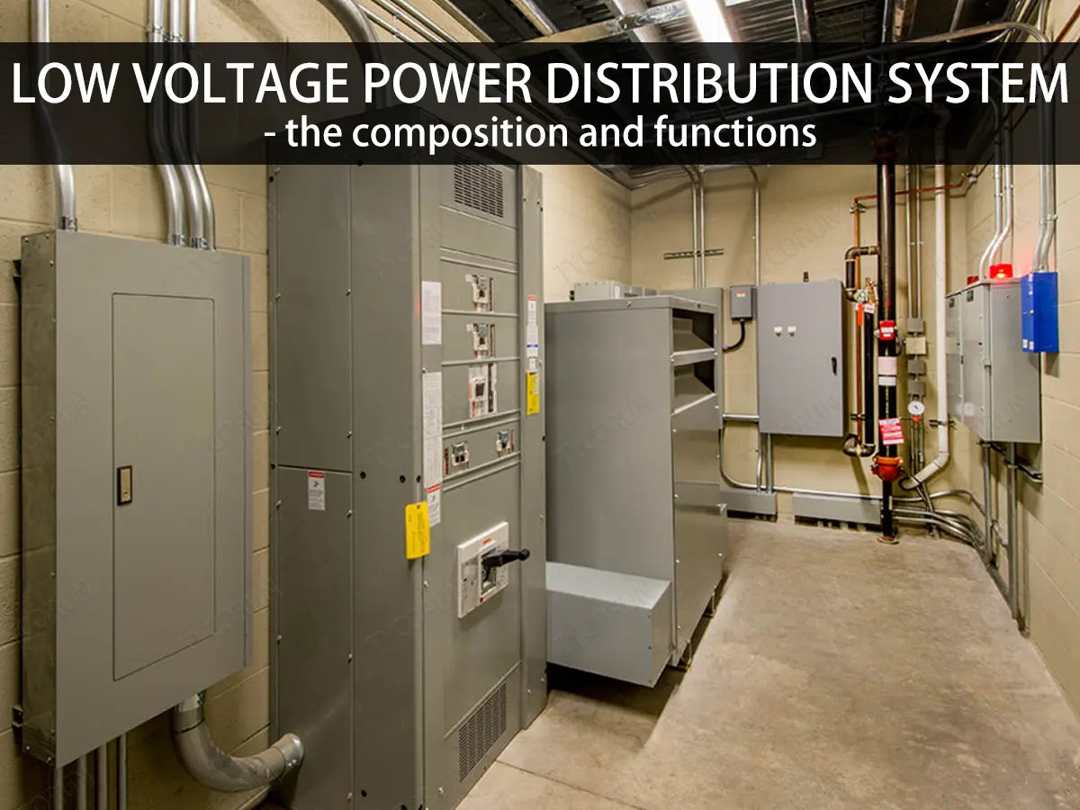
A low voltage power distribution system generally includes: low-voltage power distribution panels, switch cabinets, switch boards, lighting boxes, power boxes and motor control centers.
Low-voltage cabinet transformer section: transformer → incoming line cabinet → reactive power compensation cabinet → busbar cabinet → outlet cabinet
2. Main equipment of low voltage power distribution system
① Low-voltage incoming cabinet
- The main power incoming line is equipped with a main circuit breaker, and the front end is connected to a converter like 2000w inverter or 3000w inverter;
- The first cabinet connected from the low-voltage side output of the transformer to the initial end of the 6KV/10KV bus: it is called the incoming line cabinet, also called the variable-low incoming line cabinet;
- The incoming line cabinet is the main switch cabinet on the load side. This cabinet is responsible for the current carried by the entire busbar. The switch cabinet is connected to the main transformer and the low-voltage side load output;
- In terms of relay protection, when the busbar or circuit breaker on the low-voltage side of the main transformer fails, the over-current protection on the low-voltage side of the transformer must be used to trip the incoming line cabinet switch to remove the fault;
- Follows the functions of isolating, breaking, protecting, monitoring, and controlling the power supply quality and safety of the main circuit.

② Capacitor compensation cabinet
The function of capacitor compensation cabinet:
Unlike off grid batteries system, the grid-connected systems are greatly affected by the power quality of the grid. Capacitor compensation cabinets can improve the power factor of the low voltage power distribution system and reduce the energy waste caused by low power factor of the power grid.
Power factor:
Power factor refers to the ratio of active power to apparent power: cosφ=P/S. The size of the power factor is related to the load properties of the circuit, (such as incandescent light bulbs, resistance furnaces, etc.) The power factor of the resistive load is 1.
In circuits with inductive loads (such as motors, transformers, fluorescent lamps and electric arc furnaces, etc.), the power factor changes between 0 and 1, that is:
O<cosφ<1.
The dangers of low power factor:
- Damage the voltage quality
- Reduce the equipment service life
- Greatly increase the line losses
- Reduce the equipment utilization
- Increase the electricity expenses and thus increase the product costs
The size of the power factor is related to the load properties of the circuit. In the AC circuit, the cosine of the phase difference (Φ) between the voltage and the current is called the power factor, represented by the symbol cosΦ. Numerically, the power factor is the ratio of active power to apparent power, that is, cosΦ=P/S

The relationship between active power, reactive power and apparent power:
Due to the existence of inductive, capacitive or non-linear loads, reactive power exists in the low voltage power distribution system, resulting in active power not equal to apparent power.
The relationship between the three is as follows:
S=P+Q
S is the apparent power, P is the active power, and Q is the reactive power. The units of the three are VA (or kVA), W (or kW), Var (or kVar).
In the above formula, if the value of KVAR is zero, KVA will be equal to KW. Then 1KVA of electricity sent by the power supply bureau is equal to the user's consumption of 1KW. At this time, the cost-effectiveness is the highest, so the power factor is very important for the power supply bureau.
If the user does not achieve the ideal power factor, it is relatively consuming the resources of the power supply bureau, so this is why the power factor is a regulatory limit. Different countries and regions have different regulations. Currently, as far as China is concerned, the power factor regulation must be between 0.9 and 1 for inductance. If it is lower than 0.9, there will be punishment.
Benefits of improving power factor to user end:
- By improving the power factor, the total current in the line and the capacity of electrical components in the low voltage power distribution system, such as transformers, electrical equipment, inverter cable, etc. are reduced, thus not only reducing investment costs, but also reducing the loss of its own electrical energy.
- Ensuring good power factor values can reduce voltage losses in the low voltage power distribution system, make the load voltage more stable, and improve the quality of electric energy.
- It can increase the margin of the system and tap the potential of power supply equipment. If the power factor of the system is low, then while the capacity of the existing equipment remains unchanged, installing a capacitor can improve the power factor and increase the load capacity.
- Reduce the user’s electricity bill: By reducing the loss of the above components and improving the power factor, the electricity bill is discounted.
Specific measures to improve power factor:
Factories typically have the following load characteristics:
- Capacitive loads: servers (switching power supplies), rectifiers, UPS, LED lights
- Inductive loads: water pumps, air conditioning motors, etc.
- Resistive load: heater, incandescent lamp, etc.
How to improve power factor:
- Choose the correct model and capacity of asynchronous motor
- Select a matching transformer according to the load
- Synchronized operation of asynchronous motors
- Shunt capacitor

How parallel capacitors work
The most common method to improve the power factor is to connect reactive power compensation capacitors in parallel to the power supply equipment.
After the capacitors are connected in parallel, the current of the capacitor will offset part of the inductor current, thereby reducing the inductor current and the total current. The phase difference of the voltage and current becomes smaller and the power factor increases.
The dangers of capacitor overcompensation
- Increase electricity charges
- Increase line loss
- Reduce load voltage
Main measures to prevent capacitor overcompensation
- When capacitive load is used, the input of capacitors should be reduced or the input of reactor should be increased. The power factor should be monitored in a timely manner and the power factor should be ensured to be within 0.8-1.0 by adjusting the operating mode and switching compensation device. Adopt automatic capacitor switching device to automatically switch in or out the capacitor bank according to changes in load.
③ Low voltage contact cabinet
- Also called busbar segmentation cabinet, it is a device used to connect two sections of busbar;
- Mainly used in low voltage power distribution system with two power supplies and two transformers. The main control cabinets of the two transformers are separately wired to the contact cabinet;
- On the contact cabinet, the lower port is connected to the outlet wires of the two main controllers, that is, one uses the upper port to enter the line, and the other uses the lower port to enter the line.
- For two or more simultaneous power supply systems, when another system has a power outage or power failure, the other power supply system can provide power to the outlet cabinet of this power outage system through the contact cabinet, so that this power outage system can be used. The system's power distribution group is energized.
④ Outlet cabinet
- The outlet switch cabinet of the low voltage power distribution system, with lower-level electrical equipment;
- Install an outlet switch cabinet on the low-voltage side of the transformer to send electric energy to the low-voltage bus through the incoming line cabinet, and then to low-voltage loads or electrical equipment through the switch cabinet. This switch cabinet is an outlet cabinet.

3. Lightning protection
- Generally, the first-level arrester is installed in the main power distribution, and choose SPD with relatively large flow capacity (80KA~160KA depends on the situation), such as PT and arrester cabinet in the on-site medium voltage part;
- Install a second-level lightning arrester (10KA~40KA) at the subordinate regional distribution box, such as the lightning arrester at the front of the low-voltage entry cabinet at the installation site;
- Install a third-level signal arrester at the front end of the equipment, such as a surge protection device for wall boxes and column cabinets.
- Installing SPD (lightning arrester) requires a grounded flat iron nearby the installation site so that lightning waves can be quickly discharged when passing through the arrester;
- The grounding resistance needs to be less than 1 ohm, and in some areas with special regulations, it should be less than 4 ohms;
- Because voltage-limiting SPDs are generally used, the line length between them should not be less than 5m.
Power outage maintenance procedures
Power outage → discharge → power inspection → install grounding wire → hang signs → install barriers, etc.
Basic steps for power outage: low voltage first, then high voltage, load first and then isolation.
Related posts: global top 10 best solar inverter brands, high voltage switchgear, cost of home solar system


