

Components such as inverters, filter inductors, electromagnetic switches and fans in power electronic equipment all generate noise more or less. When the inverter is operating normally, inverter noise should not exceed 80dB, and the noise of a small inverter (such as 500w inverter or 1000w inverter)should not exceed 65dB.
So how does the inverter noise occur? Is there any way to reduce these inverter noise? This article will give you a detailed introduction.
Main content:
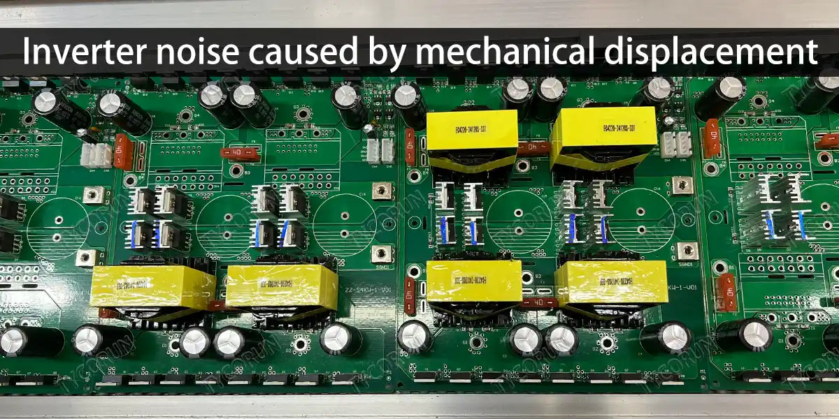
1. Inverter noise caused by mechanical displacement
In most flyback converter applications, the inverter itself is the primary source of inverter noise. There are a number of mechanisms that produce inverter noise, each producing a mechanical displacement that produces the sound. These mechanisms include:
- Relative motion: The attraction between the two parts of the core causes it to move, compressing the medium that separates them.
- Scratching: If the surfaces of two magnetic cores touch, their movement in response to magnetic flux excitation will cause the two to collide or scratch.
- Bending: A crack that exists only in the middle leg of the core in an EE or EI structure, allowing the parts of the core to follow the direction of attraction between them.
- Magnetostriction: The size of the core material changes with the magnetic flux density. The change rate of ordinary power ferrite is less than 1ppm.
- Frame movement: The displacement of the magnetic chip can be transmitted and amplified through the frame.
- Coil movement: The current in the coil creates attractive and repulsive forces that move these wires.
The moving sources work together to form a complex mechanical system, which can produce strong resonance at one or several frequency points within the hearing range of the human ear. The structure commonly used in offline flyback converters below 10W generally produces a resonance of 10kHz to 20kHz. When the fundamental frequency of magnetic flux excitation or its harmonics passes through a mechanical resonance region, the movement emits sound. Designers should change the load throughout to check the inverter noise, especially when dynamic loads are required.
The amount of inverter noise generated by these mechanisms depends on their respective locations. Fortunately, designers can apply simple structural techniques to effectively attenuate inverter noise generated by various mechanisms.
The following is a brief explanation of common methods that can effectively reduce inverter noise caused by these mechanical displacement.
- First of all, the inverter must be evenly impregnated, so that it can effectively fill the inherent gaps between coils, coils and skeletons, and between skeletons and cores, and reduce the possibility of displacement of moving parts. If necessary, it can be remagnetic. The contact surface between the component and the circuit board should be filled with white glue or sprayed with conformal anti-paint to further reduce the space for mechanical vibration and effectively reduce inverter noise.
- Reduce the peak magnetic flux density as much as possible when conditions permit, fully consider the saturation magnetic flux density at high temperatures, and leave enough margin to prevent the operating curve from entering the nonlinear zone, which can effectively reduce the inverter noise of the inverter. Experiments have proven that reducing the peak magnetic flux density from 3000 Gauss to 2000 Gauss can reduce the emitted noise by 5dB to 15dB.
- Soft magnetic materials such as amorphous and ultra-microcrystalline alloys can be used for reducing inverter noise. Their magnetic uniformity is much better than that of ordinary ferrite. The magnetostrictive effect tends to zero, so they are not sensitive to stress.
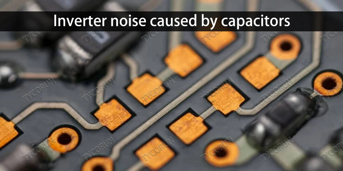
2. Inverter noise caused by capacitors
All insulating materials deform under the pressure of an electric field, and this electrostrictive effect is proportional to the square of the electric field strength. Some insulating media also exhibit a piezoelectric effect, which is a linear displacement proportional to the strength of the electric field. The piezoelectric effect is often the primary way in which inverter capacitor generates inverter noise.
The nonlinear insulating material in inexpensive small ceramic capacitors often contains a large proportion of barium titanate, which produces a piezoelectric effect at normal operating temperatures. Therefore, these components will generate more inverter noise than capacitors with linear insulating components. In switching power supplies, the capacitors in the clamp circuits with the largest voltage excursions are most likely to generate inverter noise.
Usually in order to suppress electromagnetic interference and reduce device voltage stress, switching power supplies generally use RC, RCD and other absorption circuits. The absorption capacitors often use high-voltage ceramic capacitors, and high-voltage ceramic capacitors are made of materials such as nonlinear dielectric barium titanate. Under the action of periodic peak voltages, the dielectric continues to deform, causing inverter noise.
General solutions to capacitor noise
The solution is to replace the high-voltage ceramic capacitor used in the absorption loop with a polyester film capacitor with a small electrostrictive effect, which can basically eliminate the inverter noise generated by the capacitor.
To determine whether a ceramic capacitor is a major noise source, replace it with a capacitor of a different insulator. Film capacitors are a cost-effective alternative. However, care should be taken to see if the replacement can withstand repeated spikes in current and voltage stress.
Another cost-competitive option is to replace the RCD clamp circuit with a Zener clamp circuit. The price of Zener clamps is comparable to that of RCD clamps, but they take up much less space and are more efficient.
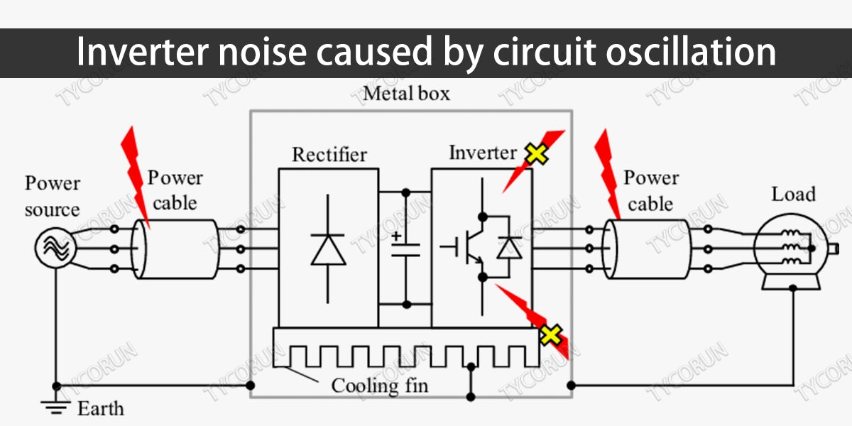
3. Inverter noise caused by circuit oscillation
When intermittent oscillation occurs during the operation of the power supply of home solar power system, it will cause the coil core to vibrate intermittently. When the oscillation frequency is close to the natural oscillation frequency of the inverter, it is easy to cause resonance, which will produce the audible inverter noise.
There are many reasons for circuit oscillation, here we will briefly introduce two of them:
① Improper PCB design
A) The power high-current ground wire and the control loop ground wire share the same trace. Since the inverter PCB copper-clad wire is not an ideal conductor, it can always be equivalent to an inductor or a resistor. When the power current flows through the PCB shared with the signal control loop line, a voltage drop occurs on the PCB, especially when multi-point grounding is used. Since the nodes of the control circuit are scattered in different locations, the voltage drop caused by the power current superimposes disturbance on the control circuit, causing the circuit to emit noise. This problem is usually solved using a single point grounding.
B) The chip VCC power supply trace is too long, or is too close to high dt/di high current traces and is interfered. This problem can generally be improved by adding a 104 ceramic decoupling capacitor close to the chip VCC pin.
C) The grounding wire of the reference voltage regulator ICTL431 is incorrect. The grounding of the same secondary reference voltage regulator IC and the grounding of the primary IC have similar requirements, that is, they cannot be directly connected to the cold ground and hot ground of the inverter. If connected together, the consequence is that the load capacity is reduced and the whistling sound is proportional to the output power.
When the output load is large and close to the power limit of the power supply, the switching inverter may enter an unstable state:
- The duty cycle of the switching tube in the previous cycle is too large, the conduction time is too long, and the power is transmitted through the high-frequency inverter.
- The DC rectifier energy storage inductor has not fully released its energy in this cycle. According to the PWM judgment, there is no drive signal to turn on the switch tube in the next cycle or the duty cycle is too small; the switch tube is in the entire subsequent cycle. In the cut-off state, or the conduction time is too short.
- After the energy storage inductor has released energy for more than one entire cycle, the output voltage drops, and the duty cycle of the switching tube will be large again in the next cycle. This goes on and on, causing the inverter to vibrate at lower frequencies (regular intermittent full cut-off cycles or frequencies with drastic changes in duty cycle), emitting lower-frequency sounds that can be heard by the human ear.
At the same time, the output voltage fluctuation will also increase compared with normal operation. When the number of intermittent full cutoff cycles per unit time reaches a considerable proportion of the total number of cycles, the vibration frequency of the inverter originally working in the ultrasonic frequency band will even be reduced, entering the frequency range audible to the human ear, and emitting sharp high frequencies. At this time, the switching inverter is working in a severe overload state and may burn out at any time - this is the reason why many power supplies "scream" before burning out.
The switching tube may also have intermittent full cut-off periods when there is no load or when the load is very light. The switching inverter also works in an overload state, which is also very dangerous. This problem can be solved by presetting a false load at the output end, but it still occasionally occurs in some high-power power supplies.
When there is no load or the load is too light, the back electromotive force generated by the inverter during operation cannot be well absorbed. In this way, the inverter will couple a lot of inverter noise signals to your 1.2 winding. This clutter signal includes many AC components with different frequency spectrums. There are also many low-frequency waves. When the low-frequency waves are consistent with the natural oscillation frequency of your inverter, the circuit will form low-frequency self-excitation, and the inverter's magnetic core will not make any sound.
② Improper feedback design
For example, if the bandwidth is set too wide and the phase margin is insufficient, the solution can be to try to reduce the bandwidth. Some designs are designed to improve the transient response. If the bandwidth is too wide, the printing of high-frequency interference will be weakened. Blindly increasing the bandwidth is not recommended.
Related posts: global top 10 best solar inverter brands, top 10 solar inverters in Australia, top 10 best inverter brands in India


