

The excitation system is the power supply and its ancillary equipment that supplies the generator's excitation current. So what does the excitation system consist of? What is their function? This article will provide you with a comprehensive introduction.
Main content:
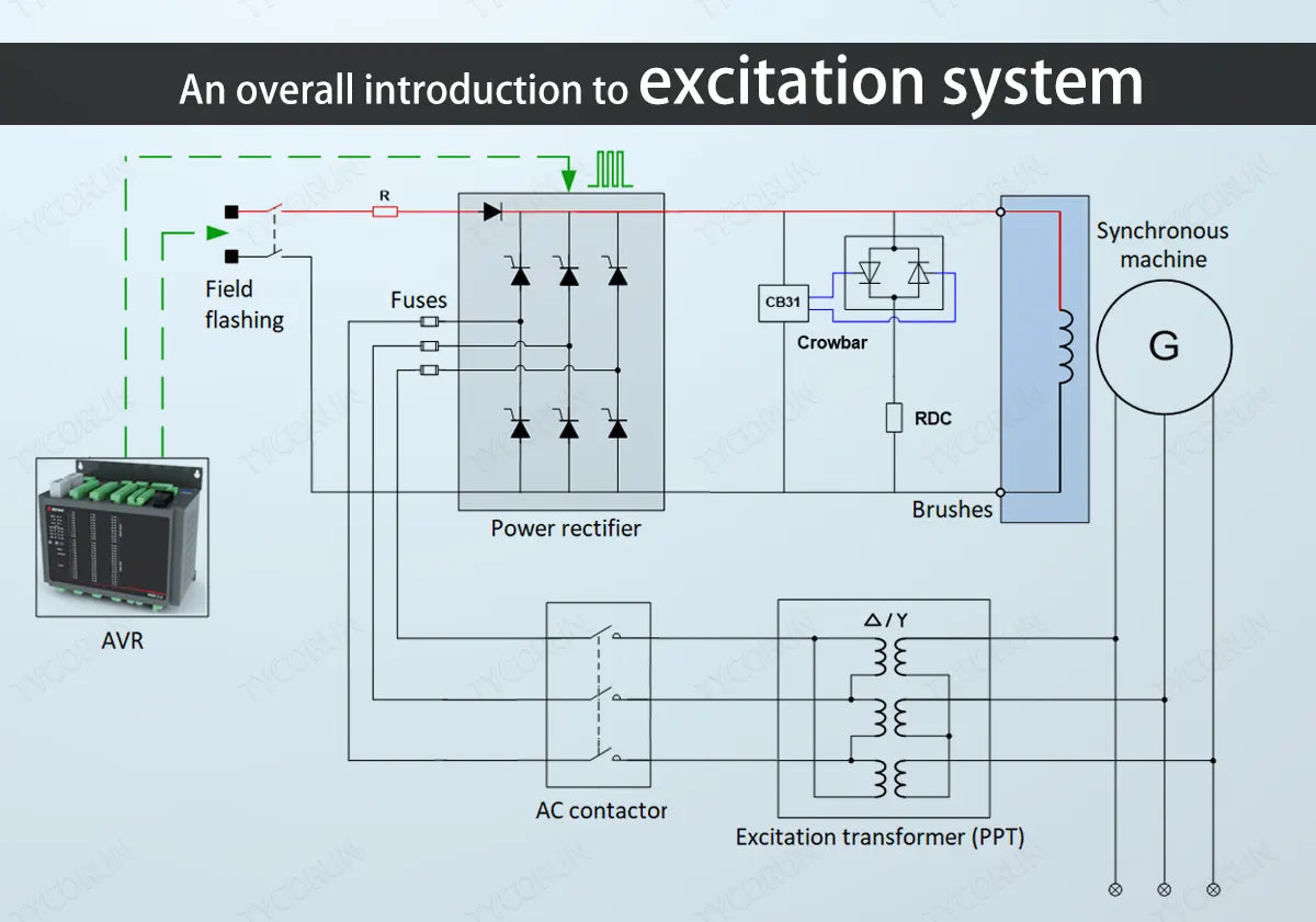
1. Composition of the excitation system
The excitation system is mainly divided into two parts: excitation power unit and excitation regulator:
- The excitation power unit provides excitation current to the synchronous generator rotor;
- The excitation regulator controls the output of the excitation power unit according to the input signal and the given regulation criteria.
For further information, you can also check the difference between inverter vs generator for RV and RV lithium battery vs generator.
2. The role of the excitation system
① Maintain the voltage level
Maintaining voltage levels is the most important task of the excitation control system, for three main reasons:
Firstly, to ensure the safety of equipment operating in the power system. The operating equipment in the power system has its rated operating voltage and maximum operating voltage. Keeping the generator terminal voltage at the allowable level is one of the basic conditions to ensure the safe operation of the generator and power system equipment. This requires the generator excitation system to be able not only to operate in a static state, but also in a steady state after a large disturbance. The generator voltage is at a given allowable level. Generator operating regulations stipulate that the operating voltage of large synchronous generators shall not be higher than 110% of the rated value.
Secondly, to ensure the economical operation of the generator. Generators are most economical when operated near rated value. If the generator voltage drops, the stator current required to output the same power will increase, resulting in increased losses. The regulations stipulate that the operating voltage of large generators shall not be lower than 90% of the rated value; when the generator voltage is lower than 95%, the generator should operate with limited load.
Thirdly, the requirements to improve the ability to maintain generator voltage and improve power system stability are consistent in many aspects. The excitation control system has a significant effect on improving static stability, dynamic stability and transient stability, and is the simplest, economical and effective measure.

② Control the distribution of reactive power of parallel operating units
The reasonable distribution of reactive power of parallel operating units is related to the regulation rate of the generator terminal voltage. The voltage regulation at the generator terminal has three regulation characteristics: no regulation, negative regulation and positive regulation.
When two or more generators with differential regulation are running in parallel, the reactive power is distributed according to the differential regulation rate. The one with a small regulation rate is allocated more reactive power, and the one with a large regulation rate is allocated less reactive power.
If the generator transformer unit is connected in parallel on the high-voltage side, since the transformer has a large reactance, if the no-difference characteristic is adopted, the unit will become differentially regulated after passing through the transformer to the high-voltage side.
If the reactance of the transformer is large, as voltage stabilizer of the high-voltage bus, the droop rate on the high-voltage bus must not be too large. At this time, the generator can adopt negative droop characteristics, which partially compensates the reactive current in the main transformer. The resulting voltage drop is also called load compensation.
The adjustment characteristics are set by the additional adjustment link in the automatic voltage regulator. For units connected to a large system, the adjustment rate Ku is adjusted between 3% and 10%.
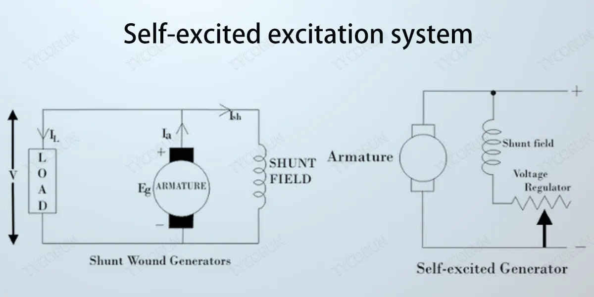
3. Self-excited excitation system
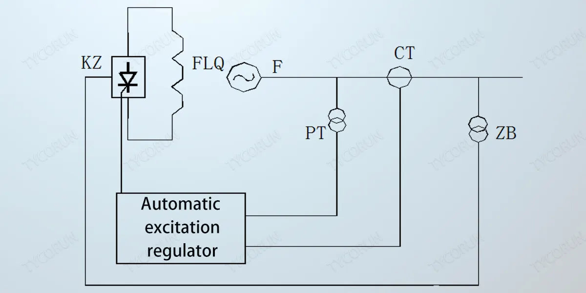
There are many types of excitation systems for synchronous generators, and the self-excited excitation system is currently widely used in power systems. The parallel excitation system in the self-excited excitation system is the most commonly used.
The parallel excitation system is the simplest excitation method for wiring in the self-excitation system. Its typical schematic is shown in the figure below. Only one excitation transformer ZB connected to the machine end is used as the excitation power supply, and the excitation of the generator is directly controlled through the silicon controlled rectifier device KZ. This excitation method is also called a simple self-excited system.
The composition of the self-excitation system
The excitation system consists of the following parts: excitation transformer, thyristor rectifier device, excitation regulator, demagnetization device and overvoltage protection device, and initial excitation device.
Advantages of parallel excitation magnetic method:
- The equipment and wiring are relatively simple;
- Since the excitation system has no rotating parts, it has high reliability;
- The excitation transformer can be placed freely, which shortens the length of the unit and reduces the cost.
- The excitation adjustment speed is fast and it is an excitation system with high initial response.
- When a three-phase fully controlled bridge is used during normal shutdown, the inverter, such as 2000w inverter or 3000w inverter, can be used to demagnetize the machine to reduce the burden on the demagnetization system.
- The generator voltage and speed of the self-shunt excitation system have a linear relationship, which is more beneficial to suppressing the voltage after load shedding than the separately excited system using a coaxial AC exciter.

Excitation transformer
The excitation transformer provides excitation energy to the excitation system. For the excitation transformer of the parallel excitation magnetic system, there is usually no automatic switch. A high-voltage fuse can be installed on the high-voltage side or not.
The excitation transformer can be set up with overcurrent protection and temperature protection. Oil-immersed excitation transformers with larger capacity are also equipped with gas protection. Most small-capacity excitation transformers generally do not have their own protection.
The high-voltage side wiring of the transformer must be included in the differential protection range of the generator. The connection group of the excitation transformer is usually the Y/△ group, and the Y/Y-12 group is usually not used. Like ordinary distribution transformers, the short-circuit voltage drop of the excitation transformer is 4% to 8%.
Silicon controlled rectifier bridge
The high-power rectifier devices in the parallel excitation magnetic system all adopt the three-phase bridge connection method. The advantage of this connection method is that the voltage withheld by the semiconductor components is low and the utilization rate of the excitation transformer is high.
The three-phase bridge circuit can adopt half-controlled or fully-controlled bridge mode. Both have the same ability to enhance excitation, but during demagnetization, the half-controlled bridge can only control the excitation voltage to zero, while the fully-controlled bridge can generate negative excitation voltage during inverter operation and rapidly reduce the excitation current to zero, feeding energy back to the grid. Fully controlled bridges are almost all used in today's parallel excitation magnetic systems.
Silicon controlled rectifier bridge adopts phase control mode
For a three-phase fully controlled bridge, when the load is an inductive load, the control angle is in the rectification state (generating forward voltage and forward current) between 0o and 90o; the control angle is between 90o and 150o (theoretically the control angle can reach 180o, but taking into account the actual commutation overlap angle and the certain width of the trigger pulse, the general maximum control angle is 150o), which is the countercurrent state (generating negative voltage and forward current).
Therefore, when the generator load changes, the excitation current is adjusted by changing the control angle of the thyristor to ensure that the generator terminal voltage is constant.
For large excitation systems, in order to ensure sufficient excitation current, several rectifier bridges are often used in parallel.
The selection principle for the number of parallel branches of the rectifier bridge is: (N+1) (N+2 is also used, but considering the increasingly mature manufacturing technology of silicon-controlled rectifier bridges and silicon-controlled rectifier bridges, the use of 2-bridge redundancy seems to have been eliminated).
N is the number of rectifier bridges to ensure normal excitation of the generator. That is, when a rectifier bridge exits due to a fault, it does not affect the normal excitation capability of the excitation system.
Excitation control device
The excitation control device includes an automatic voltage regulator and an excitation control loop. For the automatic voltage regulator in the self-parallel excitation magnetic system of large-scale units, microcomputer-based digital voltage regulators based on microprocessors are often used. The excitation regulator measures the generator terminal voltage and compares it with the given value.
When the generator terminal voltage is higher than the given value, it increases the control angle of the thyristor and reduces the excitation current, so that the generator terminal voltage returns to normal set value. When the machine terminal voltage is lower than the given value, the control angle of the thyristor is reduced, the excitation current is increased, and the generator terminal voltage is maintained at the set value.
This excitation method does not have any rotating contact components in the entire system. The schematic diagram is shown below.

In the brushless excitation system, the armature of the main exciter (ACL) rotates, and the three-phase alternating current it emits is rectified by the rotating diode rectifier bridge and then directly sent to the generator rotor circuit.
Since the main exciter armature and its silicon rectifier and the main generator rotor rotate on the same axis, there is no need for any rotating contact elements such as slip rings and brushes between them. The auxiliary exciter (PMG) in the brushless excitation system is a permanent magnet medium-frequency generator that rotates coaxially with the generator. The field winding of the main exciter is stationary, that is, it is an alternator with stationary magnetic poles and rotating armature.
The brushless excitation system completely eliminates slip rings, brushes and other rotating contact components, improving operational reliability and reducing unit maintenance workload. However, the rotating semiconductor brushless excitation method has high requirements on the reliability of silicon components. Traditional demagnetization devices cannot be used for demagnetization. The rotor current, voltage and temperature are inconvenient to directly measure.
Related posts: top 10 solar inverters in Australia, top 10 best inverter brands in India, global top 10 best solar inverter brands


