

Coupling refers to the influence between two or more systems or forms of motion through various interactions. If a wire is connected between two pendulums, their vibrations will be coupled. Coupling capacitance, also known as electric field coupling or electrostatic coupling, is a coupling method caused by the existence of distributed capacitance.
In this article, we will provide you with an overall introduction to coupling capacitor, about what it is, the working principle, functions, and applications.
Main content:
- Coupling capacitor selection reference table
- Comprehensive selection strategy for coupling capacitors
- The physics of calculation: designing for low-end clarity
- How coupling capacitor works
- Functions of coupling capacitor
- Coupling modes of coupling capacitor
- Parameters of coupling capacitor
- Applications of coupling capacitor
Coupling capacitor selection reference table
| Application Scenario | Lowest Signal Frequency | Typical Input Impedance (Rin) | Recommended Cutoff Frequency (fc) | Calculated Capacitance Range | Recommended Capacitor Type | Engineering Notes |
|---|---|---|---|---|---|---|
| High-Fidelity Audio (Line Level) | 20 Hz | 47 kΩ | ≈ 2 Hz | 1.5–3.3 µF | Polypropylene Film | Low distortion, minimal phase shift, large physical size |
| Consumer Audio (General Purpose) | 20 Hz | 10 kΩ | ≈ 2 Hz | 4.7–10 µF | Electrolytic / Film | Observe polarity if electrolytic is used |
| Microphone / Low-Level Audio | 20–50 Hz | 2–5 kΩ | 2–5 Hz | 10–47 µF | Low-Leakage Electrolytic | Leakage current and noise are critical |
| Instrument Amplifier Input | 10 Hz | 100 kΩ – 1 MΩ | ≈ 1 Hz | 0.22–1 µF | Film Capacitor | High input impedance reduces required capacitance |
| Digital Logic AC Coupling | 100 kHz+ | 50–100 Ω | ≪ Signal Frequency | 10–100 nF | C0G/NP0 Ceramic | Focus on impedance matching and edge integrity |
| RF Signal Path | 1 MHz+ | 50 Ω | ≪ Signal Frequency | 1–100 nF | C0G/NP0 Ceramic | Low ESL and stable dielectric are mandatory |
| Sensor Signal Conditioning | DC–10 Hz | 10–100 kΩ | 0.1–1 Hz | 10–100 µF | Electrolytic / Tantalum | Watch leakage and long-term drift |
Comprehensive selection strategy for coupling capacitors
Selecting an optimal coupling capacitor is a sophisticated engineering trade-off between frequency response, signal integrity, and the physical limitations of the PCB. The primary objective is to maintain signal fidelity while providing complete DC isolation. Rather than relying on empirical guesses, a systematic selection process ensures predictable and stable circuit behavior across operating conditions.
A practical coupling capacitor selection workflow typically includes the following steps:
-
Define the Signal Bandwidth
Clearly identify the lowest and highest frequencies the signal path must support. The lowest frequency determines the minimum required capacitance, while the highest frequency influences dielectric choice and parasitic considerations. -
Determine the Input Impedance of the Next Stage (Rin)
The coupling capacitor always works in conjunction with the load or input impedance of the following circuit block. This value is essential for calculating the cutoff frequency of the high-pass network formed by the capacitor and Rin. -
Calculate the Target Cutoff Frequency (fc)
For minimal amplitude loss and phase distortion, a common engineering rule is to set the cutoff frequency to approximately one-tenth of the lowest signal frequency. This provides sufficient margin for flat frequency response in the usable band. -
Compute the Required Capacitance Value
Use the first-order high-pass filter relationship
C = 1 / (2π · Rin · fc)
to determine the theoretical capacitance. In practice, select the next higher standard value to compensate for component tolerances, aging, and temperature effects. -
Select an Appropriate Voltage Rating
The capacitor’s voltage rating should exceed the maximum DC bias in the circuit by at least 20–50%. This derating improves long-term reliability, reduces dielectric stress, and minimizes parameter drift over time. -
Choose the Proper Dielectric Type
Dielectric material directly affects distortion, stability, and frequency performance. Polypropylene film capacitors are widely preferred for audio coupling due to their extremely low dielectric absorption and nonlinearity. For RF or high-frequency applications, C0G/NP0 ceramic capacitors are favored for their excellent temperature stability and low parasitic inductance. -
Evaluate ESR and Leakage Characteristics
Low equivalent series resistance (ESR) is critical in high-fidelity and high-frequency paths to avoid signal loss. Leakage current should also be considered, especially in low-level signal circuits, where it may introduce bias errors or noise. -
Consider Physical Size and PCB Constraints
Higher capacitance values and film dielectrics can significantly increase component size. The final selection must balance electrical performance with available PCB area, assembly constraints, and cost targets.
The physics of calculation: designing for low-end clarity
A coupling capacitor (C) working together with the input impedance of the following stage (Rin) forms a first-order high-pass filter that defines the low-frequency behavior of the signal path. The cutoff frequency (fc), defined as the frequency at which the signal amplitude drops by 3 dB, is given by:
fc = 1 / (2π · Rin · C)
In practical design, this equation is rearranged to determine the required capacitance:
C = 1 / (2π · Rin · fc)
To achieve professional-grade signal transparency, a widely accepted engineering rule of thumb is to design the cutoff frequency to be approximately one-tenth of the lowest signal frequency of interest. This approach minimizes low-frequency attenuation and significantly reduces phase shift within the usable bandwidth.
For example, consider a high-fidelity audio preamplifier driving a power amplifier with an input impedance (Rin) of 47 kΩ. If the design goal is to reproduce audio signals cleanly down to 20 Hz, the cutoff frequency should be set to approximately:
fc = 20 Hz / 10 = 2 Hz
Substituting these values into the capacitance equation:
C = 1 / (2π · 47,000 · 2)
The calculated result is:
C ≈ 1.69 µF
In real-world designs, engineers do not select the exact theoretical value. Instead, a higher standard value such as 2.2 µF or 3.3 µF is chosen. This deliberate margin accounts for component tolerances, temperature-dependent capacitance variation, and long-term aging, ensuring consistent low-frequency performance and preserving signal integrity under all operating conditions.
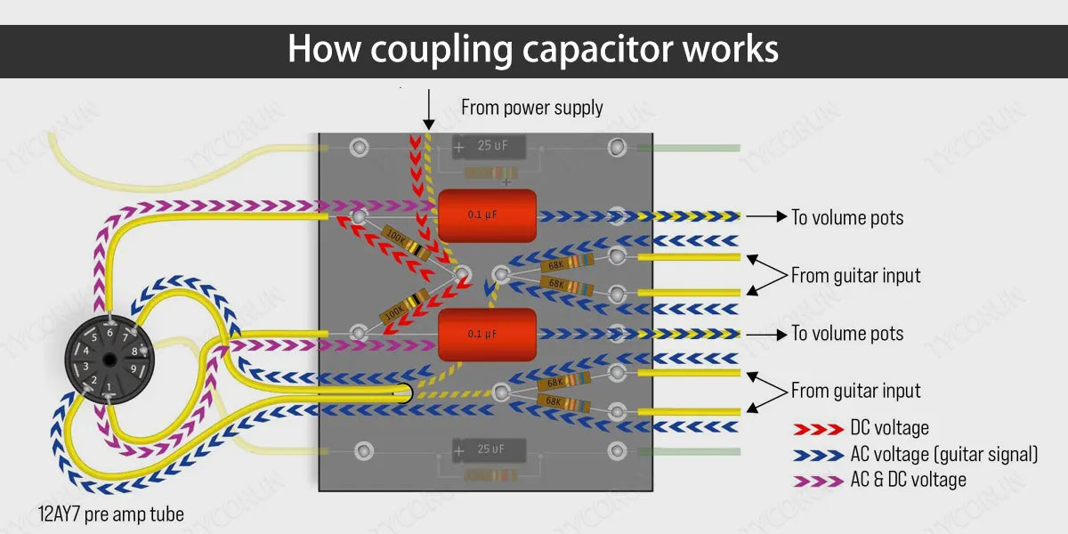
How coupling capacitor works
The coupling capacitor couples and isolates the two systems of strong current and weak current through the capacitor, providing a high-frequency signal path to prevent low-frequency current from entering the weak current system, and ensure safety.
When the capacitor is connected to an AC (alternating current) circuit, the voltage of the circuit connected to one pin gradually increases, and charge gradually accumulates on the plate where it is located. When the voltage of the circuit connected to the pin drops, the charge accumulated when the potential is high is returned to the circuit. The same is true on the other side.
The capacitor is insulated, and no current flows through the entire capacitor. However, it accumulates and releases charges as the potential rises and falls, making people mistakenly think that there is current flowing through it. Therefore, it can isolate DC, and the AC signal is coupled in the form of raising and lowering the potential at both ends and transmitted to the following battery circuit components.
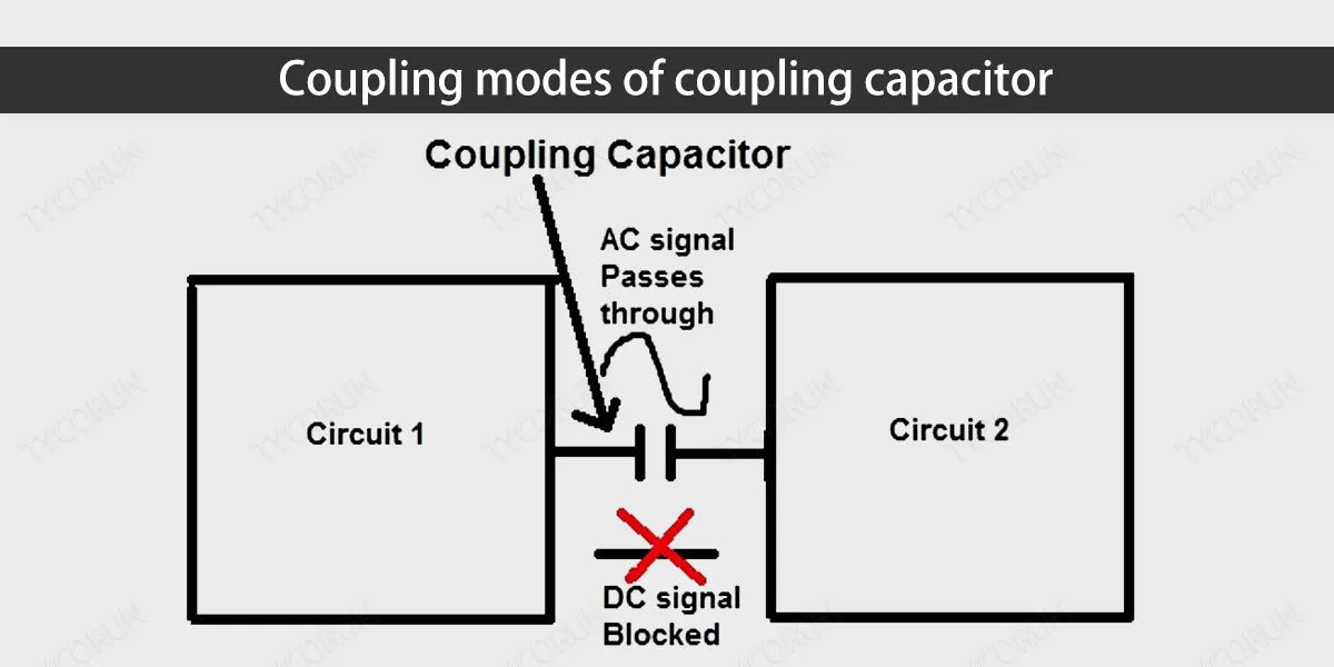
The capacitor has the characteristic of passing AC resistance and DC. As a coupling capacitor, its function is to allow the AC signal to pass normally, and to block the DC current of the upper stage amplifier circuit so that it will not affect the operating point of the next stage amplifier circuit.
Why can a capacitor allow AC current to flow through but DC current cannot? That is because the two plates of the capacitor can store charges but do not form a loop. DC can charge the capacitor, but when the voltage across the capacitor is the same as the power supply voltage, the circuit stabilizes so that no current will flow.
The capacitor is charged during the positive half cycle of the AC, and the capacitor is discharged during the negative half cycle. Such continuous charging and discharging is equivalent to the current flowing through the capacitor, forming a path.
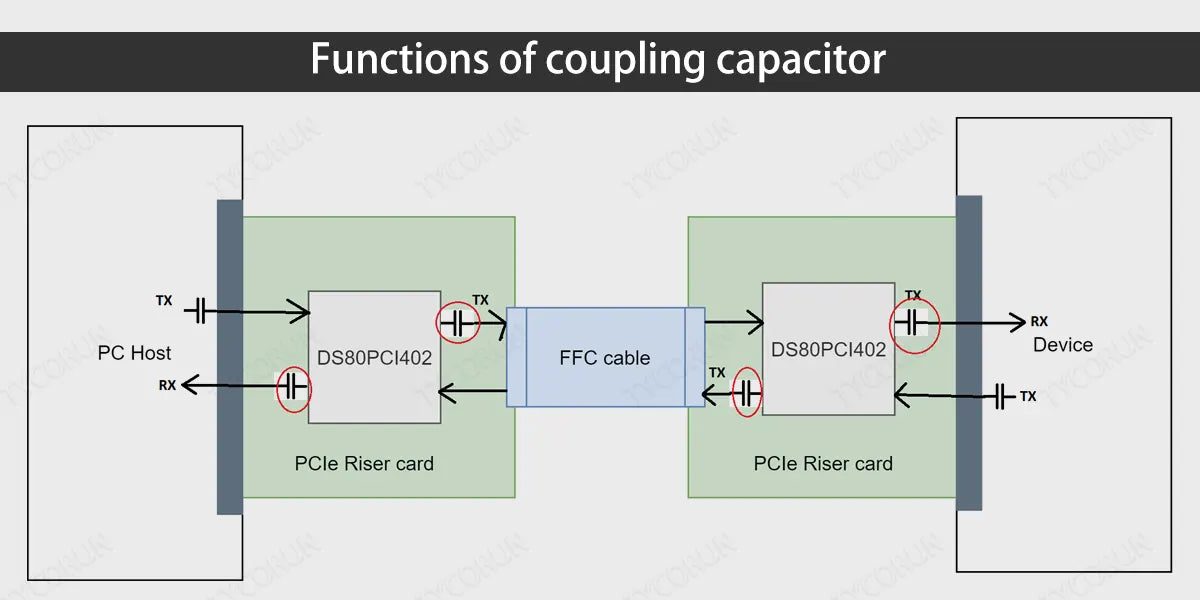
Functions of coupling capacitor
Coupling refers to the process of signal transmission from the first stage to the second stage. Generally, it refers to AC coupling when not specified. From a perspective of the circuit , it can always be distinguished into a driving power supply and a driven load.
If the load capacitance is relatively large, the driving circuit must charge and discharge the capacitor to complete the signal transition. When the rising edge is relatively steep, the current is relatively large, so the driving current will absorb a large power supply current.
Because of the inductance and resistance (especially the inductance on the chip pins will cause rebound), this current is actually a kind of noise compared to normal conditions, which will affect the normal operation of the front stage. Coupling capacitor plays a vital role in the circuits.
Here are the main functions of coupling capacitor:
- Signal transmission: Coupling capacitor is used to transfer signals from one circuit to another circuit. When there is a DC bias between two circuits, the coupling capacitor can isolate the DC component and only transmit the AC signal. In this way, the coupling capacitor helps maintain the DC operating point of the circuit while ensuring signal transmission
- Isolate the intersection: Coupling capacitor can also play a role in isolating DC and AC signals. In some circuits, DC bias may affect signal transmission and amplification. By using coupling capacitor, the DC bias can be isolated so that AC signals can be transmitted and amplified efficiently.
- Prevent voltage drift: Coupling capacitor can be used to prevent voltage drift. When capacitance is present in a circuit, the current can change over time. By using coupling capacitor, a stable voltage can be maintained and the impact of current drift on the circuit can be prevented.
- Filter: Coupling capacitors are widely used in filters in circuits. Filters are used to remove high or low frequency signals in a circuit so that only signals within a specific frequency range are transmitted. The coupling capacitor plays a role in isolating and transmitting signals in the filter, helping to achieve the filtering effect.
Coupling modes of coupling capacitor
The interference signal generated by the interference source causes electromagnetic interference to the electronic control system through a certain coupling channel. The coupling method of interference is nothing more than acting on the electronic control system through wires, spaces, public lines, etc.
And there are mainly the following types of capacitor coupling.
- Direct coupling: This is the most direct way of interference intrusion and the most common way in the system. For example, interference signals directly invade the system through wires and cause interference to the system. For this coupling method, filtering and decoupling methods can be used to effectively suppress the incoming electromagnetic interference signals.
- Common impedance coupling: This is also a common coupling method. It often occurs when the currents in two circuits have a common path. There are two types of public impedance coupling: public ground and power supply impedance. To prevent this coupling, the coupling impedance should approach zero, so that there is no common impedance between the interference source and the interfered object.
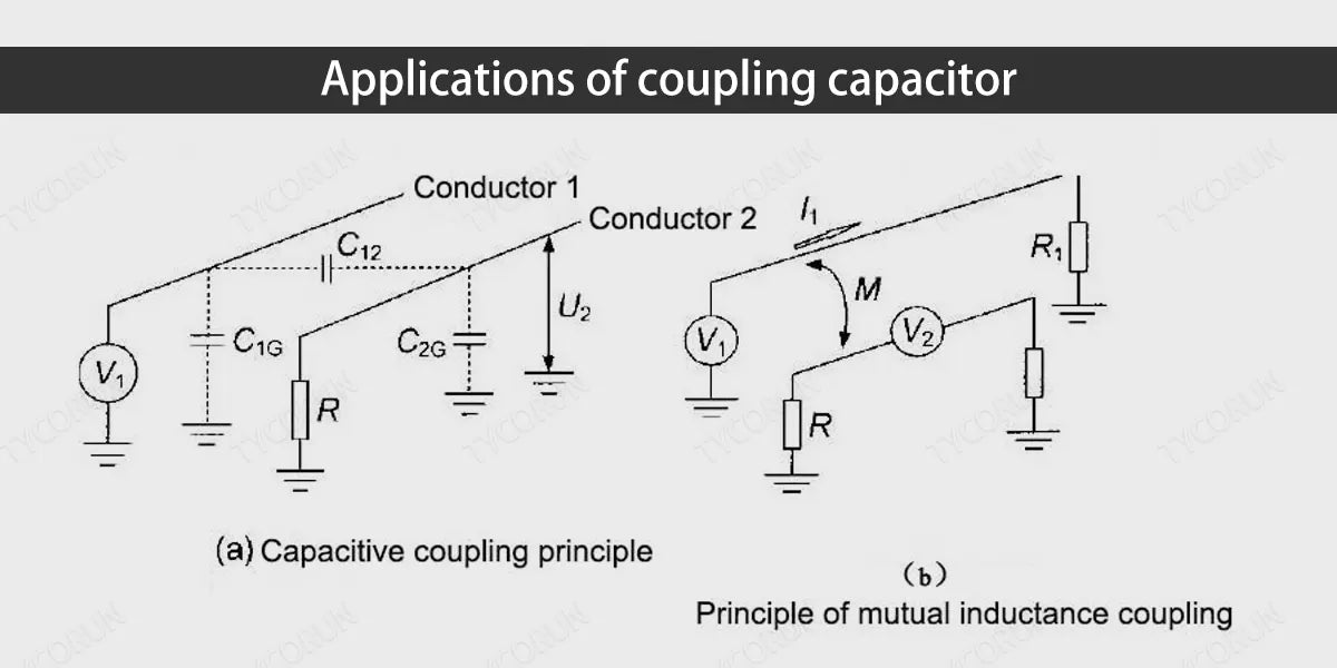
- Capacitive coupling: Also known as electric field coupling or electrostatic coupling, it is a commonly used signal coupling method in inverters like 2000 watt inverter or 3000 watt solar inverter. This method mainly utilizes capacitors to transfer signals and convert DC to AC by elevating and lowering the voltage through a transformer or other converter. Capacitive coupling is mainly used in inverter output circuits and control circuits.
- Electromagnetic induction coupling: Also called magnetic field coupling. It is a coupling method due to electromagnetic field induction in internal or external space. A common method to prevent this coupling is to shield devices or circuits that are susceptible to interference.
- Radiation coupling: Radiation of electromagnetic fields can also cause interference coupling, which is a kind of irregular interference. This kind of interference can easily be transmitted into the system through the power line. In addition, when signal transmission lines are long, they can radiate and receive interference waves, which is called the antenna effect.
- Leakage coupling: Refers to resistive coupling. This interference often occurs when insulation is degraded.
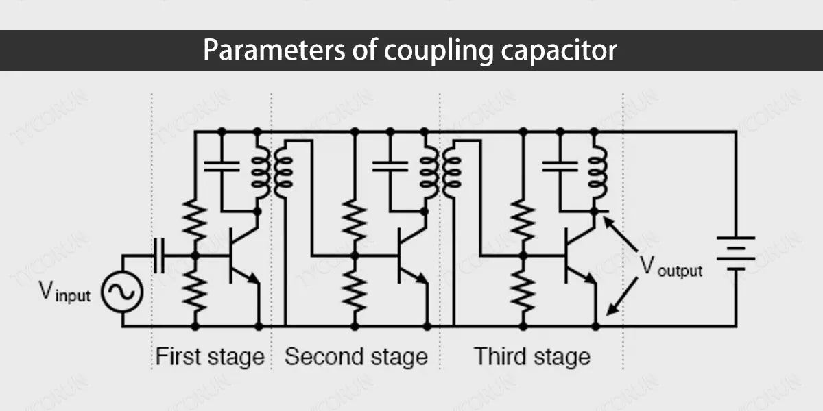
Parameters of coupling capacitor
Choosing the appropriate coupling capacitor is critical to the performance of the circuit.
Here are a few parameters to consider when selecting coupling capacitors:
- Capacity value: The capacitance of the coupling capacitor determines the transmission range of the signal in the circuit. A larger capacitance can transmit a wider frequency range, but it will also have an impact on the signal transmission speed. Therefore, according to the needs of the circuit, an appropriate capacitance value needs to be selected.
- Voltage level: The voltage rating of the coupling capacitor should match the voltage, car battery voltage for example, in the circuit. Selecting a voltage level that is too small may cause capacitor damage and circuit failure.
- Quality materials: The dielectric material of the coupling capacitor also affects its performance. Common dielectric materials include aluminum electrolytic capacitors, ceramic capacitors and polymer capacitors. Depending on the requirements of the circuit, appropriate dielectric materials need to be selected.
- Dimensions and packaging: The size and packaging of the coupling capacitor also need to be considered. Choosing the appropriate size and package ensures that the circuit is easy to install and layout and that it meets the circuit's space requirements.
Applications of coupling capacitor
Coupling capacitors are widely used in various electronic devices that work with LFP battery and circuits. Here are a few common applications:
- Amplifier: Coupling capacitor plays a key role in amplifier circuits. It is used to pass the input signal to the amplification stage of the amplifier while isolating the DC bias, so as to maintain the amplifier's operating point and ensure that the signal is effectively amplified.
- Filter: The coupling capacitor plays a filtering role in the filter circuit. For example, a high-pass filter blocks low-frequency signals and only transmits high-frequency signals. Coupling capacitors are used in filters to isolate signals and transmit signals within a specific frequency range to achieve filtering effects.
- Mixer: Coupling capacitors can also be used in mixer circuits. A mixer is used to mix two or more signals together to obtain a new frequency signal. Coupling capacitors are used in mixer circuits to transmit signals and isolate signals of different frequencies.
- Communication and cooperation: AC coupling refers to the use of coupling capacitors to connect two or more circuits together to transmit and couple signals. This type of coupling is commonly used in audio and RF (radio frequency) applications.
Related posts: AC coupling vs DC coupling, energy storage capacitor, supercapacitor battery


