

main content:
It is difficult to adjust the air-gap magnetic flux in the permanent magnet synchronous motor, which limits its constant power working range, and some complex controls (such as online optimization, etc.) are difficult to carry out. In the past ten years, the field weakening control research of PMSM has been gradually deepened, and various motor structures and field weakening control methods have emerged one after another. A large number of research results show that the field weakening speed expansion capability of PMSM can be improved more or less from the control. Such as the six-step voltage method, the feedforward field weakening scheme, the current regulator scheme, the field weakening control method based on virtual instantaneous power, the field weakening expansion method of overmodulation technology, and the field weakening expansion method of controlling the lead angle, etc. But these methods all have some problems more or less. In addition to the limitation brought by the power of the inverter, the limitation of the motor body on the field weakening expansion is more decisive. At present, there are mainly technical solutions such as composite rotor structure, structure changing magnetic flux path, hybrid excitation structure, controllable magnetic flux structure, mechanical device-assisted adjustment of magnetic flux structure, double stator winding structure, permanent magnet segmented structure, stator deep slot structure and double-segment rotor structure. This paper mainly describes three new motor topologies: dual-stator motor, hybrid permanent magnet brushless motor, and permanent magnet brushless motor based on the variable reluctance magnetic field adjustment mechanism. They adopt a new structure and control strategy, which can realize the effective control of the air-gap magnetic flux.
1. Double stator motor
According to the different installation methods of rotor permanent magnets, dual-stator motors can be divided into two types: series magnetic circuit and parallel magnetic circuit. It consists of two inner and outer stators and a cup-shaped rotor. The two stators each have a set of three-phase windings, and the rotor adopts a permanent magnet rotor. For double-stator motors with series magnetic circuit structure, tile-shaped permanent magnets are attached to the inside and outside of the cup-shaped rotor. Structurally, the double-stator motor can be designed into a single-cantilever integrated structure, a single-cantilever split structure, a double-cantilever series magnetic circuit structure, and a double-cantilever parallel magnetic circuit structure.
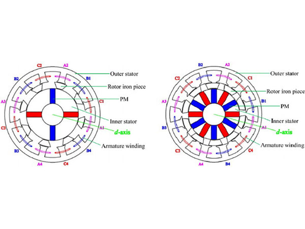
Figure 1 - Structure of a double stator motor
Regardless of the structure of the magnetic circuit of the motor, whether the motor is driven by a sine wave or a square wave, the force and energy index of the double stator permanent magnet brushless motor is higher than that of the traditional permanent magnet brushless motor. The magnitude and waveform of the electromagnetic torque of the double-stator permanent magnet brushless motor are related to the ratio of the effective series turns of the outer and inner windings and the relative position angle of the outer and inner stators. When the relative position angle of the outer and inner stators remains unchanged, the electromagnetic torque increases with the increase of the effective series turns ratio of the outer and inner windings; when other parameters of the motor remain unchanged, the electromagnetic torque will change with the relative position angle of the outer and inner stators. When the teeth of the outer and inner stators are aligned with the teeth, the motor obtains the maximum torque, and when the teeth and the slots are aligned, the motor torque is the minimum. This will help to optimize the performance of the motor while ensuring the motor torque.
The relative positions of the outer and inner stators of the double stator permanent magnet motor can be changed. When the outer and inner stators are offset by half the positioning torque cycle, and the waveform of the positioning torque half cycle is symmetrical along the wave crest axis, the positioning torque will be greatly offset.
In addition, the positioning torque of the motor can be minimized by properly selecting the pole arc coefficient of the permanent magnet, rationally configuring the length of the outer and inner air gaps and the number of outer and inner stator slots, and rationally selecting the relative positions of the outer and inner stators.
The theoretical analysis and experimental study of the flat structure double stator permanent magnet integrated starter generator prototype have proved that, the motor adopts a double-stator structure, which can ensure that the integrated starter-generator system has high power density in both electric and power generation states, and can further expand the constant power range of the motor and the constant voltage range of the generator. The detent torque can be suppressed by staggering the outer and inner stators by half the detent torque cycle. When the outer and inner stator positioning torque waveform of the dual-stator motor has good symmetry along the wave crest axis, the positioning torque can be suppressed to the maximum extent, thereby greatly improving the performance of the integrated starter-generator system. Increasing the inner stator allows the space of the motor to be effectively used . Compared with the single-stator permanent magnet synchronous prototype with the same volume and traditional structure, the rated torque of the double-stator prototype is 1.35 times that of the single-stator prototype.
Changing the relative position angle of the outer and inner stators of the motor can greatly reduce the positioning torque and electromagnetic torque ripple of the motor when the average torque of the motor is small; the rotor pole arc coefficient is 0.84~0.93 is the most suitable; in the configuration of the outer and inner air gaps, when the total air gap length of the motor is kept unchanged, the length of the outer air gap should be reduced under the requirement of ensuring the process. In terms of the number of slots, no matter how the number of motor slots is matched, the average torque of the motor is hardly affected by the relative positions of the outer and inner stators, but the torque ripple shows a different trend. Motors with integer slots have a better trend, while other fits show complex changes.
Dual-stator motors can provide a variety of connections when generating electricity over a wide speed range. In order to obtain a flexible combination of armature winding connection methods, a matrix converter with multiple power switches, a dual-rotor motor drive system, and a variety of control methods and power flow regulation methods are required. When the motor is used as a generator, the inner and outer stators of the motor can supply power to the outside respectively, or the inner and outer stator armature windings can be connected in series to improve the power generation capacity. When the windings are connected in series, the magnitude of the voltage vector sum of the two stator windings is changed by changing the relative position angle of the inner and outer stators, so as to realize the adjustment of the combined output voltage of the dual stator windings and solve the problem that the voltage of the permanent magnet generator is difficult to adjust.
2. Hybrid permanent magnet brushless motor
In the hybrid permanent magnet brushless motor, an excitation winding is added, and the magnetic field is the result of the combined action of the water magnet and the excitation winding, so that the required air gap magnetic field can be obtained. The hybrid permanent magnet brushless motor has the following characteristics.
①By changing the magnitude and direction of the excitation winding current, the air gap magnetic flux density can be easily adjusted.
②Adjust the excitation current of the excitation winding so that the two magnetic fields are superimposed and enhanced, and the motor can provide higher torque, which is beneficial to the vehicle's starting, climbing and accelerating overtaking.
③Adjust the excitation current of the excitation winding so that the two magnetic fields are superimposed and weakened, and the motor can provide a wider constant power working range, which is beneficial to the vehicle cruise control.
④ By adjusting the air gap magnetic flux density online, the motor can keep the voltage constant during power generation or regenerative braking in a wide speed range, which is beneficial to the charging of the battery pack.
⑤ By adjusting the air-gap magnetic flux density online, the motor can achieve optimal efficiency control, which is beneficial to the operation of electric vehicles.
Chan C.C. and Chau K.T. of the University of Hong Kong, Professor Cheng Shukang of Harbin Institute of Technology, etc. have conducted in-depth research on this type of motor, analyzed and designed a variety of prototypes, such as double stator claw pole rotor hybrid permanent magnet brushless motor, double salient hybrid permanent magnet brushless motor, outer rotor double salient hybrid permanent magnet brushless motor, hybrid magnetic circuit multilateral coupling motor, multiple air gap motor, etc., and made great progress.
3. Permanent magnet brushless motor based on variable reluctance magnetic field adjustment mechanism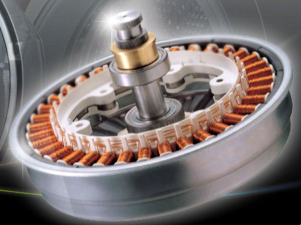
Figure 2 shows the overall structure of a typical permanent magnet brushless motor (variable magnetic reluctance PMSM, VMRPMSM) based on a variable reluctance magnetic field adjustment mechanism. The stator structure of the motor is the same as that of the ordinary permanent magnet synchronous motor. The rotor consists of a main permanent magnet, an auxiliary permanent magnet, a permanent magnet slot and a non-magnetic body. As shown in Figure 2, the non-magnetic body is embedded on both sides of the permanent magnet slot, and the main permanent magnet can move freely in the permanent magnet slot. In view of the particularity of the structure of the VMRPMSM motor, the main permanent magnet cannot occupy the entire permanent magnet slot. It is necessary to ensure the space for the main permanent magnet to move in the slot, and to ensure that the main permanent magnet can provide a large enough excitation flux. Therefore, choosing a tangentially magnetized rotor structure with a multi-pole pair number with magnetic concentration can make up for the lack of a large space for the movement of the main permanent magnets of the rotor. In addition, the magnetic circuit of the stator teeth and yoke of the multi-pole pair motor is short, and the tooth width and the height of the yoke can be designed to be smaller, the diameter ratio of the rotor to the stator is increased, and the rotor area is enlarged. In addition, the permanent magnets are rectangular tin-iron-boron permanent magnets that can be magnetized relatively uniformly. NdFeB permanent magnets are easy to corrode due to the large amount of iron and tin, so their surface should be coated.
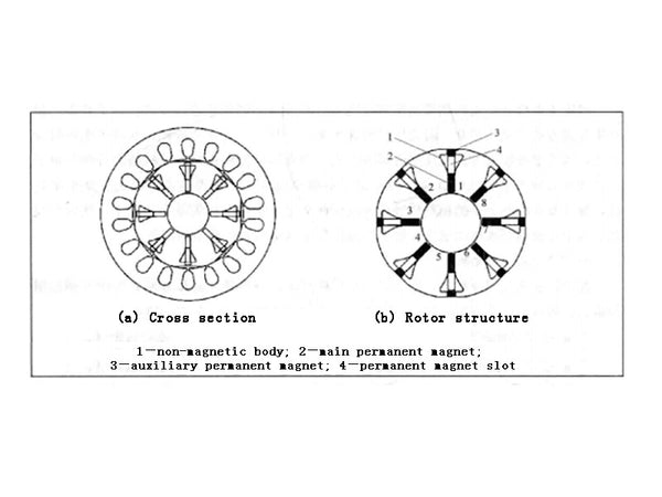
Figure 2 - Structure of a VMRPMSM motor
A non-magnetic body is introduced into the rotor structure of the VMRPMSM motor. Unlike the traditional magneto, the main permanent magnet in the rotor is no longer fixed in the slot, but can move in the permanent magnet slot. The difference between the mathematical model of the d and q axes of the motor and the traditional motor is that the coupled flux linkage of the rotor permanent magnet on the stator is a function of speed. The permanent magnets in the VMRPMSM rotor have motion characteristics, and the permanent magnets can achieve steady-state operation under the balanced action of magnetic field force, friction force and centrifugal force. The analysis results show that less motor turns, thinner permanent magnet thickness and thicker non-magnetic body are more beneficial to increase the field weakening speed range of VMRPMSM motor. This kind of motor has the advantages of simple field weakening control method, easy speed adjustment, wide speed adjustment range and high efficiency.
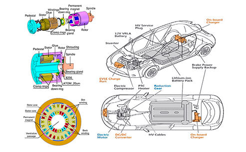
It must be pointed out that the development of the electric vehicle motor drive system so far is no longer limited to the design and application of a specific motor drive form. The latest development trend is the integration of the motor drive system. The integration of the drive system includes subsystem integration (including motor body and controller integration, multiple controllers integration, controller and DC/DC converter integration, etc.), physical structure integration (such as PCU integration in THS), thermal management integration (especially the integration of double-sided heat dissipation devices), and the integration of new devices (such as highly integrated, highly intelligent 1GBT modules), etc. Among them, the integration of motor and gear mechanism is a very important trend, which has received more and more attention and application in the field of electric vehicle motor drive technology. Among them, Toyota's THS system is a very successful commercialization case in this regard.


