

The power system of a pure electric vehicle is mainly composed of a motor and an energy storage system. The design of the motor mainly includes the rated power and operating speed range. During the system design phase, the constraints of rated voltage and space arrangement are also taken into account. The design of the motor needs to meet the requirements of the system. The following introduces the design method and process of the rated power of the motor. The design of the energy storage system will be introduced in the Design of Hybrid Vehicles section.
The torque-speed characteristic curve of the motor is mainly composed of three parts, namely: constant torque area, constant power area and natural characteristic area. The torque-speed characteristic curve of the motor is shown in Figure 1. When the motor reaches the rated power, the speed at which the motor outputs the rated torque is the basic speed or the rated speed of the motor. After exceeding the rated speed, the motor runs in constant power mode, and the torque decreases smoothly at a certain ratio, which is inversely proportional to the speed. By weakening the magnetic field, the motor can operate in the high speed range of the constant power region. After entering the natural characteristic area, the speed of the motor is higher, and the torque drops rapidly and is inversely proportional to the square of the speed. The natural characteristic area is a very important part of the overall torque-speed curve of some motors and can be used to reduce the output power of the motor. But in most cases, the vehicle's top speed is set at the end of the constant power zone. As shown in Figure 1, the operating torque and speed range in different regions: Based on the power electronics feed of the motor assembly, the motor can operate at any point within the envelope. In vehicles such as pure electric vehicles, the wide operating speed range of the electric machine makes it unnecessary to use multiple gear ratios and clutches. Therefore, the motor and the transmission shaft can be connected with the drive train with only a single transmission ratio, and the design size of the gear can be reduced by using the motor to expand the constant power characteristic area.
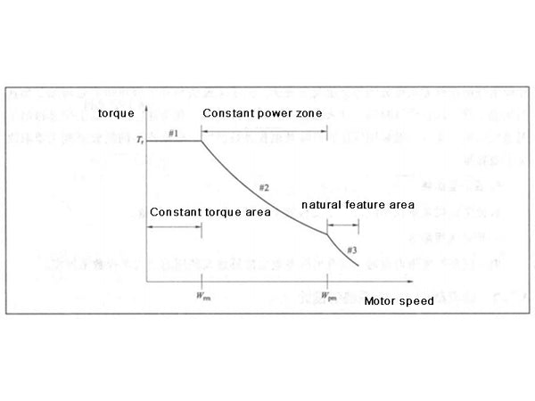
Figure 1 Motor torque-speed characteristic curve
The maximum torque required to drive the vehicle determines the size of the motor. The greater the torque of the motor, the greater its size. For a given rated speed, in order to reduce size and weight, the motor is designed with a high speed operating area. The higher speed of the motor is matched with the lower speed of the wheels through a gear train. For light passenger cars, the wheel speed is generally about 1000r/min, the corresponding motor speed is about 15000r/min, and the gear reduction range of the drive train is 10:1~15:1, divided into two 3:1~4:1 deceleration stage. The size of the gears is determined by the high or low speed performance of the vehicle, and further by the power rating of the vehicle.
As shown in Figure 2, the traction force-speed characteristic curves of the drive system under different transmission ratios are very different. First, depending on the gear ratio, the speed of the motor can be translated into the speed of the power transmission unit or the speed of the wheels. Smaller gear ratios result in higher wheel speeds or vehicle speeds, but the powertrain will have less traction, which reduces the initial acceleration and maximum gradeability of the vehicle; if the powertrain uses a larger gear ratio, the increased Effective peak traction on the big wheels, but the top speed Vmax will be reduced to a certain extent. Therefore, the gear ratio of the drive train depends on factors such as the rated speed of the motor, the rated and maximum speed of the vehicle, the radius of the wheels, and the maximum gradeability. But it must be noted that a high gear ratio results in a larger gear size. Therefore, both the gear ratio and the rated motor speed should be selected to optimize the overall size and performance of the drive train.
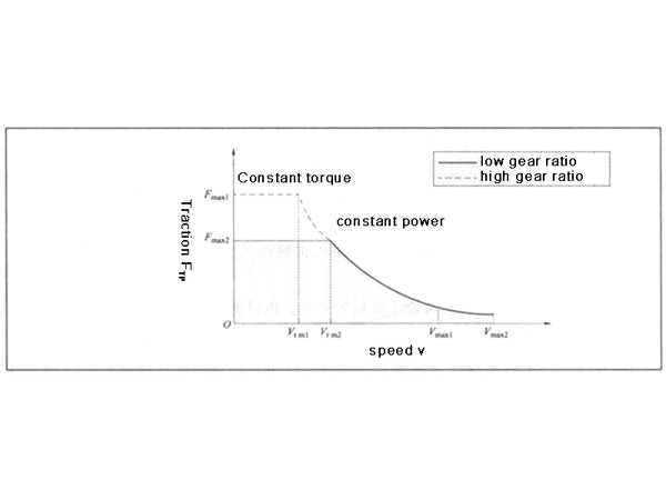
Figure 2 Traction-speed characteristic curve of the drive system under two gear ratios
Next, we discuss motor design targeting specified conditions such as initial acceleration, rated speed for a given gradient, maximum steady-state speed, and maximum gradient. The following parameters will be used in the design and calculation, namely the rated power Pm of the motor, the rated speed of the motor ωrm, the rated speed of the wheel ωfwh, the rated speed of the vehicle νf, the total mass of the vehicle m, the windward area of the vehicle Af, the wheel The rolling resistance coefficients C0 and C1, and the air resistance coefficient CD. The design is usually based on a set of known parameters or some well-founded assumptions at the beginning stage, and after repeated adjustment and verification, the calculation is ended when the final calculated value meets the requirements.
1) Initial acceleration
The initial acceleration refers to the acceleration at which the vehicle speed increases from 0 to vf in a time of length tf. vf is the rated speed of the vehicle, which is calculated by multiplying the circumference of the wheel by the rated speed of the wheel (ie vf=2π·ωfwh·rwh). The initial acceleration a of the vehicle can be calculated by formula (1):
a=dv/dt=(FTR-FRL)/m——(1)
In the formula: FTR—the traction force of the vehicle, which is generated by the vehicle drive unit, and drives the vehicle to move forward at the desired speed, N;
FRL—road load force, that is, the reaction force, including the component force of gravity, tire rolling resistance and air resistance, N;
m—mass of the vehicle, kg.
Among them, the determination of the vehicle traction force FTR needs to use the following parameters, including vehicle mass, rolling resistance, air resistance, slip rate, wheel radius, etc. Some of these parameters are known, and the rest need to be assumed.
According to the given traction force-speed curve, the differential equation in equation (1) is solved to obtain the rated power condition of the motor: when t=0, the vehicle speed v=0; when t=tf, the vehicle speed v=vf.
Under the conditions of t∈(0~tf) and vehicle speed v∈(0~vf), integrating the differential equation in Eq. (1), we get
m∫vt0[dv/FTR-FRL(v)]=∫tr0dt——(2)
When the product of the rated speed of the wheel and the transmission ratio is higher than the rated speed of the motor, the torque-speed characteristic of the motor is located in the constant power region, so the integral on the left side of the equal sign in equation (2) can be divided into two speed regions, and the vehicle speed is 0 ~vrm is constant torque mode, and the vehicle speed is in constant power mode when vrm~vf, the formula (2) can be written as
m∫vr0[dv/[(Pm/vrm)]-FRL(v)]+m∫vfvrm[dv/[(Pm/vrm)]-FRL(v)]=tf——(3)
According to rolling resistance, air resistance and road gradient, the road load force FRL can be written as a function of speed. By solving the transcendental equation in equation (3), the power Pm and rated speed of the motor at the rated vehicle speed vf can be obtained. In practical applications, the use of a large number of computer-aided design and simulation is helpful for the determination and optimization of the power transmission system motor rated power and transmission ratio. When FRL=0, the rated power of the motor is
Pm=(m/2tf)(v²rm+v²f)——(4)
It can be seen from formula (4) that when vrm=0, the rated power of the motor is the smallest, indicating that the motor is the smallest motor that meets the requirements when it is fully working in the constant power mode; if the motor is fully working in the constant torque mode, that is, vrm =vf, then the motor power is twice the former. Considering that it is impossible to completely work in the constant power region except for the constant torque region in actual use, the motor should be designed to have a lower basic speed or rated speed and have a wide constant power region.
2) Rated speed
The power system is designed to have sufficient power to accelerate the vehicle from 0 to rated speed, and to cruise at rated speed (assuming that the initial acceleration at the specified road gradient is unknown in cruise conditions).
3) Maximum speed
The traction power of the vehicle when cruising at vmax is
PTR.max=mgvmaxsinβ+[mgC1+(ρ/2)AFCD]v3max+mgvmaxC0——(5)
When the vehicle is running at high speed, its output power is mainly used to overcome the air resistance which increases cubically. Since the vehicle is required to have high acceleration performance, Pm is actually larger than PTR·max. If PTR·max is greater than Pm that satisfies the initial acceleration requirement, then PTR·max can be defined as the rated power of the motor. The natural mode area of the motor can meet the requirements of the maximum speed of the vehicle, thereby reducing the size of the motor.
4) Maximum grade
Under the condition of known motor and transmission ratio, the maximum grade of the vehicle can be derived from formula (6)
Ipmax-[100FTR]/√[(mg)²-F²TR]——(6)
Substitute the initially designed maximum traction force FTR of the motor into Equation (6) to check whether the maximum gradeability meets the requirements. If the maximum motor power at the maximum acceleration or maximum speed cannot meet the requirements of the maximum grade of the vehicle, the rated power or gear ratio of the motor needs to be increased. It's worth mentioning that increasing the gear ratio doesn't affect top speed. By coordinating and matching the transmission ratio and motor power, the application requirements are met, while the motor and gear set are maintained at a reasonable size.


