

An inverter is a device that converts direct current into alternating current. Most commercial, industrial, and residential loads require AC power, but AC power cannot be stored in batteries, the storage of which is important for backup power.
Today, this drawback can be overcome with DC power supplies. The polarity of DC power does not change over time like AC power, so DC power can be stored in high capacity lithium battery. So we can first convert the AC power into DC power, and then store it in the battery.
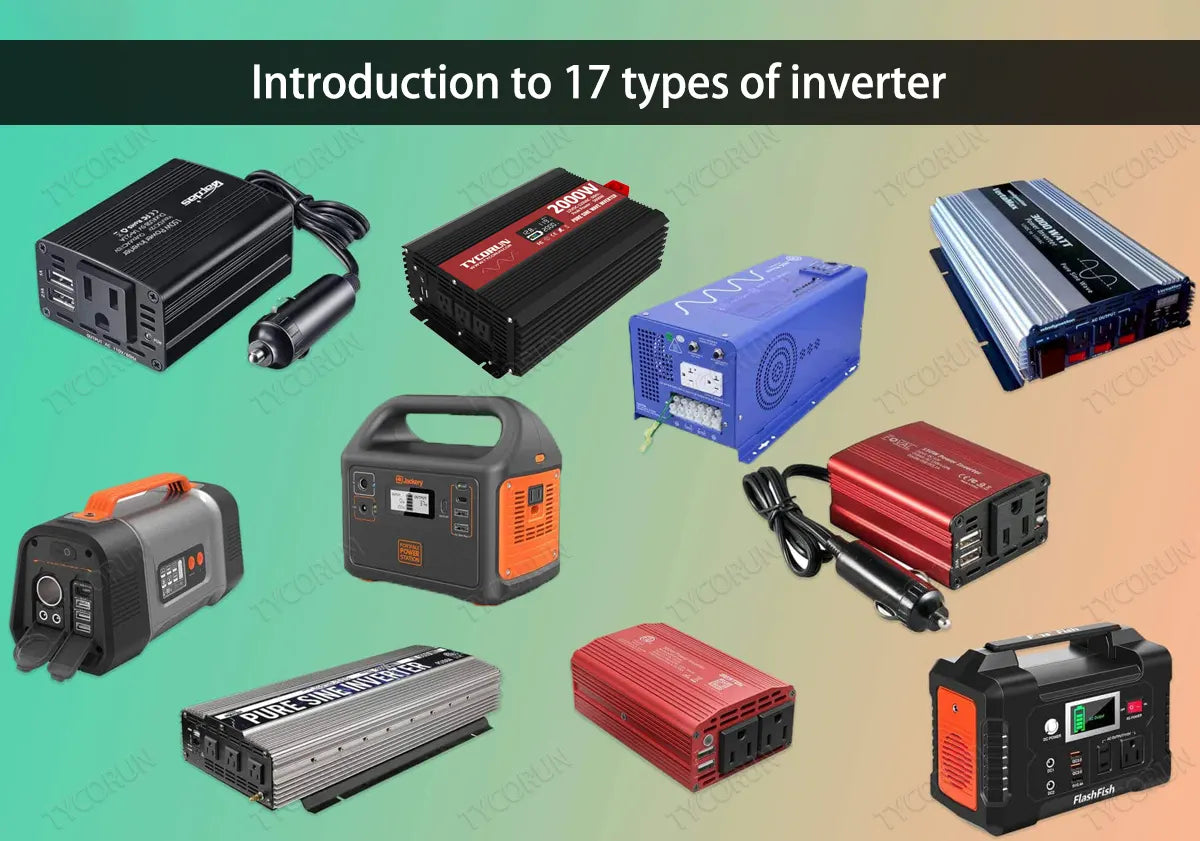
In this way, whenever AC power is needed to run AC appliances, the DC power will be converted back to AC power to run AC appliances. Based on the application's input source, connection method, output voltage waveform, etc.,there are 17 types of inverter. Different types of inverter have different characteristics, and we will see it.
Main content:
1. Classification by input source
The input of the inverter can be a voltage source or a current source, so these types of inverter are divided into voltage source inverter (VSI) and current source inverter (CSI).
- Voltage source inverter (VSI)
When the input of the inverter is a constant DC voltage source, the inverter is called a voltage source inverter. A voltage source inverter has a rigid DC voltage source at its input with zero impedance. In practice, the impedance of a DC voltage source is negligible.
Assuming that the VSI is powered by an ideal voltage source (very low impedance source), the AC output voltage is completely determined by the state of the switching devices in the inverter and the applied DC source.
- Current source inverter (CSI)
When the input of the inverter is a constant DC current source, the inverter is called a current source inverter. Rigid current is supplied to the CSI from a DC power source, which has high impedance. Typically, a large inductor or a closed-loop control current is used to provide rigid current. The resulting current wave is rigid and unaffected by the load.
The AC output current is completely determined by the switching devices in the inverter and the state of the DC applied power supply.
2. Classification by output phase
According to the output voltage and current phase, there are two types of inverter: single-phase inverters and three-phase inverters.
- Single phase inverter
Single-phase inverters convert DC input into single-phase output. The output voltage/current of a single-phase inverter has only one phase, and its nominal frequency is a nominal voltage of 50Hz or 60Hz. Nominal voltage is defined as the voltage level at which an electrical system operates.
There are different nominal voltages, namely 120V, 220V, 440V, 690V, 3.3KV, 6.6KV, 11kV, 33kV, 66kV, 132kV, 220kV, 400kV and 765kV. Low nominal voltages can be achieved directly through an inverter using an internal transformer or buck-boost circuit, while for high nominal voltages an external step-up transformer is used. Single phase inverters are used for low loads.
Single-phase losses are greater, and single-phase efficiency is lower than three-phase inverters. Therefore, three-phase inverters are the first choice for high loads.

- Three-phase inverter
A three-phase inverter converts DC power into three-phase power. A three-phase power supply provides three channels of alternating current with evenly separated phase angles. All three waves produced at the output have the same amplitude and frequency, but vary slightly due to the load, while each wave is 120 degrees phase-shifted from each other.
Basically, a single three-phase inverter is 3 single phase inverters where the phases of each inverter are 120 degrees apart and each single phase inverter is connected to one of the three load terminals.
3. Classification by commutation technology
According to the commutation technology, it can be divided into two main types: line commutation and forced commutation inverters. In addition, there are also auxiliary commutation inverters and complementary commutation inverters, but since they are not commonly used, we briefly discuss the two main types of inverter here.
- Line commutated inverter
In these types of inverter, the line voltage of the AC circuit is available through the device. When the current in the SCR experiences a zero characteristic, the device is turned off. This commutation process is called line commutation, and the inverter that works based on this principle is called a line commutated inverter.
- Forced commutated inverter
In these types of inverter, there is no zero point in the power supply. This is why some external source is needed to rectify the device. This commutation process is called forced commutation, and the inverter based on this process is called a forced commutation inverter.
4. Classification by connection method
According to the connection method of thyristors in the circuit, it can be divided into 3 types of inverter: string inverter, parallel inverter and bridge inverter. Bridge inverter is divided into half bridge, full bridge and three-phase bridge.
- String inverter
A string inverter consists of a pair of thyristors and an RLC (resistor, inductor and capacitor) circuit. One thyristor is connected in parallel with the RLC circuit, and one thyristor is connected in series between the DC power supply and the RLC circuit. These types of inverter are called a string inverter because the load is directly connected in string with the DC source with the help of thyristor.
String inverters are also called self-commutated inverters because the thyristors of this inverter are self-commutated by the load. Another name for these types of inverter is "load commutated inverter", because the LCR is the load that provides commutation.

- Parallel inverter
The parallel inverter consists of two thyristors, a capacitor, center-tapped transformer and an inductor. Thyristors are used to provide a path for the current to flow, while inductors are used to make the current source constant.
The switching on and off of these thyristors is controlled by commutation capacitors connected between them. The reason why it is called a parallel inverter is that in the working state, the capacitor is connected in parallel with the load through the transformer.
- Half bridge inverter
A half-bridge inverter requires two electronic switches to operate. The switch can be a MOSFET, IJBT, BJT or thyristor. Half-bridges with thyristors and BJT switches require two additional diodes except for purely resistive loads, while MOSFETs have built-in body diodes.
In short, two switches are enough for purely resistive loads, while other loads (inductive and capacitive) require two additional diodes. These diodes are called feedback diodes or freewheeling diodes. The working principle of half-bridge types of inverter is the same for all switches, but here we are talking about half-bridge with thyristor switches.
There are two complementary thyristors, which means one thyristor is conducting at a time. For resistive loads, the circuit operates in two modes. The switching frequency will determine the output frequency. When the output frequency is 50HZ, each thyristor is turned on for 20ms at a time.
- Full bridge inverter
A single-phase full-bridge types of inverter has four controlled switches that control the direction of current flow in the load. The bridge has 4 feedback diodes that feed the energy stored in the load back to the power supply. These feedback diodes only work when all thyristors are off and the load is not a purely resistive load.
For any load, only 2 thyristors are working at a time. Thyristors T1 and T2 will conduct in one cycle and T3 and T4 in another cycle. In other words, when T1 and T2 are in the ON state, T3 and T4 are in the OFF state, and when T3 and T4 are in the ON state, the other two are in the OFF state. Turning on more than two thyristors at once can cause a short circuit, generate excessive heat and burn out the circuit immediately.
- Three-phase bridge inverter
Industrial and other heavy loads require three-phase power. In order to run these heavy loads from storage devices or other DC sources, a three-phase types of inverter is required. Three-phase bridge inverter is another type of bridge inverter that consists of 6 controlled switches and 6 diodes.
5. Classification by operating mode
Based on the operating mode, there are 3 main types of inverter: stand-alone inverters, grid-tied inverters and bimodal inverters.
- Standalone inverter
Standalone types of inverter are connected directly to the load and are not interrupted by other power sources. Stand-alone inverters are types of inverter that power the load on their own without being affected by the grid or other power sources.
These types of inverter are called off-grid mode inverters because these inverters are not affected by the utility grid. These inverters cannot be connected to the utility grid because they do not have synchronization capabilities, where synchronization is the process of matching the phase and nominal frequency (50/60hz) of two AC sources. And they can work with off grid batteries system.

- Grid-tied inverter
A grid-tied inverter (GTI) has two main functions. One function is to provide AC power from a storage device (DC source) to an AC load, while another function is to provide additional power to the grid.
Grid-tied inverters, also known as utility-interactive inverters, grid-interconnected inverters, or grid-feedback inverters, synchronize the frequency and phase of electrical current to suit the utility grid. Power is transferred from the DC source to the utility grid by increasing the voltage level of the inverter voltage.
- Bimodal inverter
Bimodal inverters can operate both as grid-connected inverters and as stand-alone inverters. These types of inverter can inject additional energy from renewable energy sources and storage devices into the grid, and withdraw power from the grid when the energy generated by renewable energy sources is insufficient. In other words, these inverters can operate as stand-alone inverters and grid-tied inverters depending on the load requirements.
Bimodal inverters are multifunctional and include the functions of stand-alone inverters and grid-tied inverters. The functionality of a bimodal inverter changes with the load. If there is a problem with the grid or when the power of the renewable energy source is enough to satisfy the load, its function changes to a standalone inverter (it becomes a standalone inverter).
In this case, the transfer switch disconnects the inverter from the grid. Once renewables start producing additional energy, the operating mode changes from stand-alone to grid-connected mode. The inverter synchronizes its phase and frequency with the inverter and starts injecting additional energy into the grid.
6. Classification by output waveform
An ideal inverter is one that converts a DC signal into a pure sinusoidal AC output. The problem with real inverters is that their output signal is not purely sinusoidal. According to the output waveform, inverters are divided into square wave inverters, quasi sine wave inverters and pure sine wave inverters.
- Square wave inverter
These types of inverter are the simplest inverters that convert DC to AC, but the output waveform is not the desired pure sine wave. These inverters have square waves at the output. In other words, these inverters convert DC input into AC in the form of a square wave. At the same time, square wave inverters are also cheaper. The simplest structure of these inverters can be H-bridge inverters.
A simpler version can be achieved using a SPDT (Single Push Double Throw) switch before the transformer as shown in the picture. The transformer will also help achieve any desired output voltage level. The working operation of the given model is extremely simple. Simply turning the switch on and off simultaneously changes the current at the output.
In other words, switching a SPDT at the desired frequency will produce an AC square wave at the output of a typical inverter (i.e. a center tapped transformer). The harmonic distortion of a typical sine wave is about 45%, which can be further reduced by using a filter that will filter out some of the harmonics.
- Quasi sine wave inverter
Quasi-sine wave inverter or simply modified sine wave inverter with stepped sine wave. In other words, the output signal of these inverters steps up with positive polarity. After hitting the positive peak, the output signal begins to gradually decrease until it reaches the negative peak.
The structure of a quasi-sine wave inverter is much simpler than a pure sine wave inverter, but more complex than a pure square wave inverter. Although the final output waveform of these inverters is not a pure sine wave, the harmonic distortion of the output is still reduced to 24%. Filtering further reduces distortion, but the amount is still significant.
For this reason, these inverters are not the first choice for driving a variety of loads including electronic circuits. Quasi-sine waves can permanently damage electronic devices that have timers in their circuits. All appliances with motors will not work as efficiently if connected to a quasi-sine wave inverter as if connected to a pure sine wave inverter.
Additionally, rapid transitions in the waveform may cause noise. Due to these problems, the application of quasi-sinusoidal inverters is limited.

- Pure sine wave inverter
Pure sine inverters convert DC to almost pure sine AC. The output waveform of a pure sine wave inverter is still not an ideal sine wave, but it is much smoother than square wave and quasi-sine wave inverters. The output waveform of a pure sine wave inverter has extremely low harmonics. Harmonics are sine waves with varying amplitudes that are odd multiples of the fundamental frequency.
Harmonics can cause serious problems in various appliances and can be further reduced by using various PWM techniques and then passing the output signal through a low-pass filter. The construction and operation of pure sine wave inverters is much more complex than square wave and modified square wave inverters. For further information, you can click to check the best 2000w pure sine wave inverter and 3000w inverter.
These inverters are better than the previous two types of inverter because most electrical devices require pure sine waves to run better. As mentioned before, square wave or quasi-sine wave inverters can damage appliances, especially those with motors in them. Therefore, for practical purposes pure sine inverters are more commonly used.
7. Classification by the number of output levels
The number of output levels of any inverter can be at least two or more. Depending on the number of output levels, there are two types of inverter: two-level inverters and multi-level inverters.
- Two-level inverter
These types of inverter have two output levels. The output voltage alternates between positive and negative, and at the fundamental frequency (50Hz or 60Hz). Some two-level inverters have three levels in their output waveform. The reason why three-level inverters fall into this category is because 1 of the levels is zero voltage.
A two-level inverter circuit consists of a source and some switches that control current or voltage. Two-level inverters are limited in their high-frequency operation in high-voltage applications due to limitations in switching losses and device ratings. However, the rating of switches can be increased through string and parallel combinations.
The set of switches in a two-level inverter that provides the positive half cycle is called the positive set of switches, while the other set of switches that provides the negative half cycle is called the negative set. Two-level inverters are not preferred for the following reasons.
Inverters need to operate using a minimum number of switches and a minimum power source to convert power in small voltage steps. Smaller voltage steps will provide higher quality waveforms. Additionally, it reduces voltage (dv/dt) stress on the load and electromagnetic compatibility issues. Therefore, multi-level inverters are a more practical first choice.

- Multi-level inverter
Multi-level inverters convert DC signals into multi-level staircase waveforms. The output waveform of the multi-level inverter is not direct positive and negative alternation, but multi-level alternation. Since the smoothness of the waveform is directly proportional to the number of voltage levels, multilevel inverters produce smoother waveforms. As mentioned above, this property makes it useful for practical applications.
Different types of inverters are available from Tycorun, please check 3000 watt car inverter, 2000 watt inverter, 1000 watt inverter, 500 watt inverter
Related posts: Photovoltaic power generation system, Inverter fan, Inverter battery


