

Main content:
1. stand-alone operating DC system of the wind power generation system
The figure below is a circuit diagram of a small DC generator driven by a stand-alone operating wind turbine to supply power to a resistive load through an energy storage device. In the figure, L represents the resistive load (such as lighting, etc.) . When the system stand-alone operating, the wind power decreases and the speed of the wind turbine decreases, so that when the voltage of the DC generator in stand-alone operating is lower than the voltage of the battery bank, the stand-alone operating of the wind turbine cannot charge the battery, but the battery must react to the stand-alone operating of the wind turbine. to send electricity. In order to prevent this from happening, a moving break contact controlled by a reverse current relay is installed between the armature circuit of the stand-alone operating wind turbine and the battery pack. When the voltage of the stand-alone operating DC generator is lower than the voltage of the battery pack, the reverse current relay acts, Disconnecting the "break contact" prevents the battery from supplying reverse power to the generator.
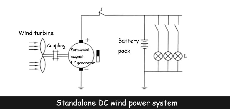
In the stand-alone operating of wind power generation system with battery pack as energy storage device, the selection of battery pack capacity is very important, because this is the key factor to ensure continuous power supply to the load during the no-wind period. Generally speaking, the choice of battery capacity It is related to the rated value of the selected stand-alone operating wind turbine, daily load , and the wind condition in the installation area of the stand-alone operating wind turbine, etc., and at the same time The charging and discharging current value of the battery pack should also be calculated according to the 10 h discharge rate current value (the best charging and discharging current value of the battery) to ensure the rational use of the battery and prolong the service life of the battery.
2. Stand-alone operation AC system of the wind power generation system
The following figure is the current schematic diagram of the stand-alone operating silicon rectifier generator charging the battery. If a resistive DC load is added to the positive and negative ends of the battery, it will form a rectifier set by the stand-alone operating AC wind turbine. After charging the battery and supplying power to the DC load, if an inverter is connected to the positive and negative terminals of the battery, it can supply power to the AC load.
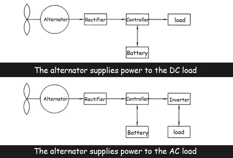
In a stand-alone operating wind power system, the inverter can be a single-phase inverter or a three-phase inverter, depending on whether the load is single-phase or three-phase. Lighting and household appliances only need a single-phase AC power supply, and a single-phase inverter is selected; for power loads, a three-phase inverter must be used, and the shape of the stand-alone operating AC power output by the inverter can be sine wave or square according to the load requirements. Wave.
In addition to the stand-alone operating of the permanent magnet alternator and the stand-alone operating of the silicon rectifier self-excited alternator, the stand-alone operating alternator can also be a silicon rectifier self-excited alternator that uses an stand-alone operating brushless excitation. There is no slip ring on the rotor of the generator, so it is more reliable to work. The working principle of the brushless excitation silicon rectifier self-excited alternator is shown in the figure below.
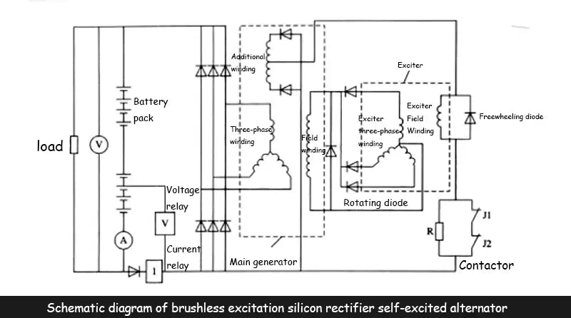
The stand-alone operating of the brushless excitation silicon rectifier self-excited alternator is composed of two parts: the main generator and the exciter. The exciter is a pivot type, that is, the three-phase winding of the exciter and the excitation winding of the main generator are in The stand-alone operating main generator is on the same rotating shaft, and is connected with the wind turbine rotating shaft through the coupling and gearbox. In the stand-alone operating main generator, in addition to the stator three-phase winding and the rotor excitation winding, there are additional windings, the exciter The field winding is stationary.
When the stand-alone operating wind turbine drives the rotor of the main generator to rotate, due to the residual magnetism of the generator, an induced electromotive force is generated in the additional windings of the generator, and the stand-alone operating DC current obtained after full-wave rectification by the diode is used as the excitation current, which flows through the excitation At this time, the stand-alone operating wind turbine and the three-phase winding of the exciter rotate coaxially, so an stand-alone operating AC electromotive force is induced in the three-phase winding, and then passes through the three-phase half-wave rectification of a rotating diode in each phase connected to it. The stand-alone operating generated DC power is supplied to the excitation winding of the main generator. After the excitation winding of the stand-alone operating main generator is energized, an alternating induced electromotive force is generated in the three-phase winding of the main generator; The induced electromotive force increases in the exciter, which increases the current in the field winding of the exciter, which in turn increases the current in the three-phase winding of the exciter and the field winding of the main generator, resulting in induction in the three-phase winding of the main generator. The electromotive force also increases accordingly; repeating this, the induced electromotive force in the three-phase winding of the main generator becomes larger and larger, and finally tends to be stable and completes the process of establishing the voltage.

In order to control the voltage and current value of the stand-alone operating main generator to not exceed its rated value when supplying power to the load, voltage and current slitting appliances can be installed in the main circuit of the stand-alone operating main generator to control the contactor on and off respectively. Contacts J1 and J2, when the wind speed increases and the output voltage of the stand-alone operating main generator is higher than the rated value, the voltage relay stand-alone operating and the J1 contact opens, the excitation current of the exciter will flow through the resistance R, and the current will decrease, The excitation current of the main generator decreases, thus forcing the output voltage of the main generator to drop; when the wind speed drops and the output voltage of the stand-alone operating main generator drops to a certain level, the voltage relay is reset, the J1 contact is restored, and the generator output voltage It is raised again, and so continuously adjusted, can keep the output voltage of the main generator around the rated value. When the current of the stand-alone operating main generator exceeds the rated value, the current relay operates, the J2 contact opens, and the resistance R is connected to the excitation winding circuit of the exciter. The output current also drops.
Read more: Independent operation of wind power system generators


