

Main content:
- 1. Independently run the DC generator of the wind power generation system
- 1.1 Basic structure and principle of DC generator in independent operation wind power generation system
- 1.2 Self-excitation of shunt DC generators independent operation
- 2. Independent operation the wind power system alternator
1. Independently run the DC generator of the wind power generation system
1.1 Basic structure and principle of DC generator in independent operation wind power generation system
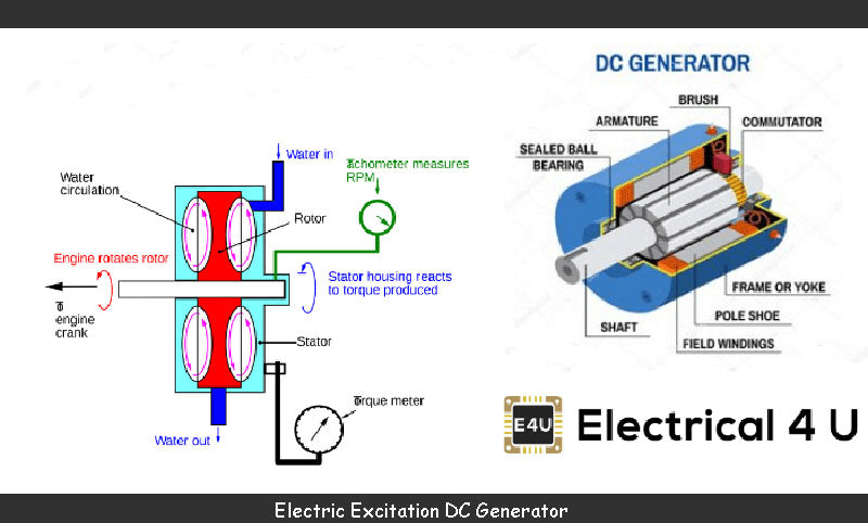
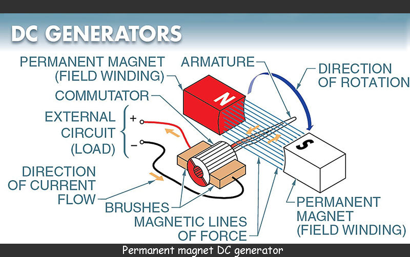
Small-capacity wind power plants in the earlier period generally used small DC generators. In terms of structure, there are two types of independent operation wind power generation system permanent magnet type and independent operation wind power generation system electric excitation type. Independent operation wind power generation system permanent magnet DC generator uses permanent magnets to provide the excitation magnetic flux required by the generator; The electric excitation DC generator of the independent operation wind power generation system uses the excitation coil to generate the excitation flux. Due to the difference in the connection between the excitation winding and the armature winding, it is divided into two forms: separate excitation and shunt excitation (self-excitation).
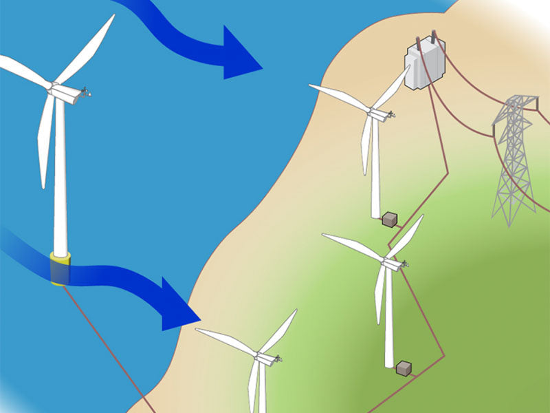
In the independent operation power generation device, when the DC generator of the independent operation wind power generation system is driven by the wind turbine to rotate, according to Faraday's law of electromagnetic induction, an induced potential is generated in the armature winding of the DC generator of the independent operation wind generation system, If the outlet end of the armature is connected to the load, there will be current flowing to the load, that is, there will be electric energy output at the a and b ends, and the wind energy will be converted into electric energy.
1.2 Self-excitation of shunt DC generators independent operation
When using an independent operation running shunt generator, in order to establish the voltage, in the case that the independent operation running generator has residual magnetism, the polarity of the excitation winding must be connected in parallel to the two ends of the armature to be correct, and the total resistance of the excitation circuit must be less than a certain Critical value at rotational speed, if the polarity of the parallel connection to both ends of the armature is incorrect (i.e. the field winding is reversed), the magnetomotive force generated by the current in the independently running field circuit will reduce the residual flux in the generator, independently The terminal voltage of the running generator cannot be established, that is, the motor cannot be self-excited.
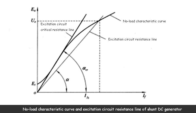
If the resistance value of the strings in the excitation circuit of independent operation increases, the resistance of the excitation circuit of independent operation is tangent to the no-load characteristic curve, and there is no stable intersection point, and a stable voltage cannot be established.
As can be seen from the figure below, at this time α σ>α,, the resistance value corresponding to thisR σ = tanα σ,, this α σ is the critical resistance value, so in order to establish the voltage, the total resistance of the excitation circuit Rf+r f must be less than the critical resistance value.
It must be noted that if the total resistance of the independent generator excitation circuit can be self-excited at a certain speed, when the speed is reduced to a certain speed value, it may not be self-excited. This is because the no-load characteristic curve is related to the speed of the generator. proportional. When the speed decreases, the no-load characteristic curve also changes its shape. Therefore, for the resistance value of a certain independent operation excitation circuit, there is a corresponding minimum critical speed value. If the generator speed is less than that, it cannot be self-excited. In the independent operation of small wind power plants, in order to make the generator establish a stable voltage, when designing the wind power plant, it should be considered that the speed value determined by the wind turbine speed regulating mechanism should be greater than the minimum critical speed value of the generator.
2. Independent operation the wind power system alternator
2.1 Independent operation of permanent magnet generator of wind power generation system
(1) The characteristics of the permanent magnet generator of the independent operation of the wind power generation system. There is no excitation winding on the rotor of the permanent magnet generator of the independent operation wind power generation system, so there is no copper loss of the excitation winding, which is more efficient than the independent operation of the electric excitation generator of the same capacity: there is no slip ring on the rotor, and the operation is safer and more reliable; the motor It is light in weight, small in size and simple in manufacturing process, so it is widely used in small and micro generators. The disadvantage of permanent magnet generators is that the voltage regulation performance is poor.
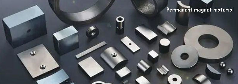
(2) Permanent magnet material. The key to running a permanent magnet motor independently is the permanent magnet material. The main technical parameters that characterize the performance of the permanent magnet material are B r (residual magnetic flux density), B c (coercive force), (BH) max (maximum magnetic energy product), etc. , There are two kinds of permanent magnet materials commonly used in small and micro independent wind turbines, ferrite and NdFeB. Due to the high price of AlNiCo and Pengco materials and the low maximum magnetic energy product, they are not economical and are not used much. The price of ferrite materials is low, the Hr is high, it can run stably, and the utilization rate of permanent magnets is high, but the (BH) max of iron oxide is about 3.5×10⁷OeGs (Gao Austrian), B r is below 4000Gs (Gauss), The (BH) maxof NdFeB is (25~40)× 106OeGs, the total efficiency of the independent operation motor can be higher, so under the same input mechanical power, the output electrical power can be improved, so in the micro and small wind independent More of this material is used in the operation of generators, but compared with ferrite, the price is more expensive. No matter what kind of permanent magnet material, it must be magnetized in the permanent magnet machine to obtain magnetism.
(3) The structure of the permanent magnet motor independent operation. The permanent magnet generator stator is the same as the ordinary AC motor, including the stator iron core and the stator winding. The three-phase winding or single-phase winding of the stator is placed in the stator core slot.
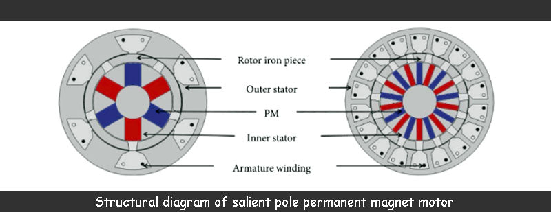
According to the arrangement and shape of the permanent magnets, the rotors of the independent operation permanent magnet generators are classified into two types: salient pole type and claw pole type.
The magnetic flux of the salient-pole permanent magnet motor independent operation is as follows: N pole - a certain air gap, sub-cogging - air gap - S pole, forming a closed magnetic flux loop.
The magnetic flux of the claw pole permanent magnet motor independent operation is as follows: N pole-left claw pole air gap stator-right claw pole-S pole. The N and S poles of the Л pole are staggered, and the air gap between the claw pole and the stator core is much smaller than the gap between the left and right claw poles, so the magnetic flux will not be directly formed by the N pole claws entering the S pole claws Short circuit, the left claw pole and the right claw pole are made of the same shape.

In order to achieve the effect of high efficiency and saving permanent magnet materials in the design of the independent operation permanent magnet motor, the working point of the permanent magnet material of the independent operation permanent magnet motor should be close to the maximum magnetic energy product. save.
2.2 Independent operation of silicon rectifier self-melting alternator
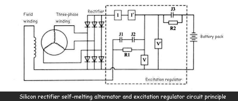
(1) Structure, working principle and circuit diagram. The circuit diagram of the independent operation operated silicon rectifier self-excited alternator is shown in the figure below. The stator of the generator is composed of a stator iron core and a stator winding. The stator winding is three-phase, Y-shaped connection, placed in the inner groove of the stator iron core, and the rotor It is composed of rotor iron core, rotor winding, slip ring and rotor shaft. The rotor iron core can be made into salient pole type or claw type, and claw poles are generally used. Both ends of the rotor excitation winding are connected to the slip ring. The brushes in contact are connected to the DC output of the silicon rectifier to obtain the DC excitation current.
Most of the wind turbine blades of small wind turbines that independent operation is of fixed pitch. When the wind force changes, the speed of the wind turbine will change accordingly, and the speed of the generator connected to the wind turbine will also change, and the outlet of the generator will also change. The voltage will also fluctuate, which will cause the DC voltage output by the independent operation silicon rectifier and the excitation current of the independent operation generator to change, and cause the excitation magnetic field to change, which will cause the output voltage of the independent operation generator to fluctuate. The reaction makes the fluctuation range of the generator outlet voltage continue to increase. Obviously, if the voltage fluctuation is not controlled, in the case of independent power supply to the load, the quality of power supply will be affected, and even electrical equipment will be damaged. In addition, wind turbines that independent operation is equipped with battery packs, and voltage fluctuations will lead to overcharging of the battery packs, thereby reducing the service life of the battery packs.
In order to eliminate the fluctuation of the output voltage of the generator, the independent operation silicon rectifier alternator is equipped with an excitation regulator. As shown in the figure above, the independent operation excitation regulator is composed of a voltage-dimensional electric appliance, a current-slit electric appliance, a countercurrent relay and its controlled actuators. It is composed of breaking contacts J1, J2, moving and closing contacts J3 and resistors R1 and R2.
(2) The working principle of the independent operation excitation regulator. The function of the independently operated excitation regulator is to enable the generator to automatically adjust its excitation current (that is, the excitation magnetic flux) to offset the influence of the generator speed change caused by the wind speed change on the generator terminal voltage.
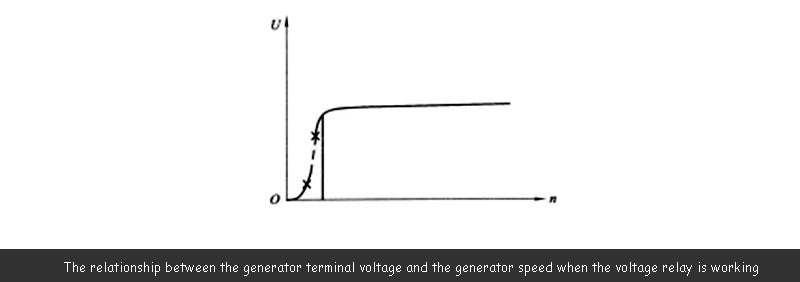
When the speed of the independent operation generator is low and the terminal voltage of the independent operation generator is lower than the rated value, the voltage relay V does not act, its dynamic break contact J1 is closed, and the output terminal voltage of the silicon rectifier is directly applied to the excitation winding, and the independent operation generator generates electricity. The generator belongs to the normal excitation state; when the wind speed increases, the speed of the independent operation generator increases, the terminal voltage of the independent operation generator is higher than the rated value, the dynamic break contact J1 is disconnected, the resistance R1 is connected in the excitation circuit, and the excitation current and The magnetic flux decreases accordingly, and the output voltage of the independent operation generator also decreases; when the generator voltage drops to the rated value, the contact J1 is closed again, and the independent operation generator returns to the normal excitation state. The relationship between the generator terminal voltage and the generator speed when the voltage relay is working is shown in the figure below.
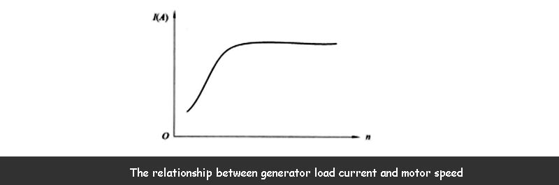
When the independent operation wind turbine is running, when the user inputs too much load, the load current may be too large and exceed the rated current. The service life has a greater impact, and even damages the stator windings of the generator. The function of the current relay is to suppress the overload operation of the generator. The moving contact J2 of the current relay I is connected in series in the excitation circuit of the generator, and the load current output by the independent operation generator passes through the winding of the current relay. When the output current of the independent operation generator is lower than the rated value, the relay does not work, the dynamic breaking contact is closed, and the generator is in a normal excitation state; when the output current of the independent running motor is higher than the rated value, the dynamic breaking contact J2 is broken. Open, the resistor R1 is connected to the excitation circuit, and the excitation current is reduced, thereby reducing the output voltage of the generator and reducing the load current. When the current relay is working, the relationship between the load current of the independent running generator and the speed of the motor is as shown in the figure below.
In order to prevent the battery pack from sending electricity to the generator excitation winding when there is no wind or the wind speed is too low, that is, the battery pack changes from the charging operation to the reverse discharge state, which will not only consume the energy stored in the battery, but may also burn the excitation winding. In the excitation regulator device, a counter current seam electric device is also installed. The reverse current seam electrical appliance is composed of voltage coil V', current coil I', moving contact J3 and resistance R2. When the generator is working normally, the suction force generated by the voltage coil of the reverse current relay and the current flowing in the current coil closes the moving contact J3; when the wind speed is too low and the terminal voltage of the independent operation generator is lower than the voltage of the battery pack, the relay The reverse current flows through the current coil instantaneously, and the magnetic field generated by this current is opposite to the magnetic field generated by the current flowing in the voltage coil. Therefore, the suction force of the total magnetic field generated by the current in the voltage coil and the current coil is weakened, so that the moving contact J3 is disconnected, thereby disconnecting the circuit for the battery to transmit power to the generator excitation winding.
Compared with the independent operation of permanent magnet generator, the silicon rectifier alternator with independent operation excitation regulator is characterized in that it can automatically adjust the output voltage of the generator with the change of wind speed, prevent overcharging of the battery, and prolong the use of the battery At the same time, it also realizes the overload protection of the generator, but the dynamic breaking contact of the excitation regulator operating independently, due to its frequent opening and closing actions, it is necessary to make appropriate treatment for the contact material and arc breaking performance .
When using an independent operation alternator for wind power generation, the speed of the generator must reach the voltage at this speed before the battery can be charged.
2.3 Independent operation capacitor self-excited asynchronous motor
It is known from the theory of independent operation of asynchronous generators that when the independent operation of asynchronous generators is connected to the grid, the excitation current is supplied by the grid. This excitation current is capacitive current to the induced potential of the asynchronous motor. When the asynchronous generator runs independently, in order to obtain this capacitive current, a capacitor must be connected to the output end of the independent operation generator, thereby generating a magnetic field and establishing a voltage.
Read more: Research on Power Load Line of Wind Power Load Regulation System


