

The diaphragm itself is not only a poor conductor of electrons, but also has the characteristics of electrolyte ion passing. The diaphragm material must have good chemical and electrochemical stability, good mechanical properties, and maintain a high degree of wettability to the electrolyte during repeated charging and discharging. The interface compatibility between the separator material and the electrode and the retention of the separator to the electrolyte all have an important impact on the charge and discharge performance and cycle performance of lithium-ion batteries.
Commonly used separator materials for lithium-ion batteries include fiber paper or non-woven fabrics, and porous membranes made of synthetic resin. Common diaphragms are polypropylene and polyethylene porous membranes. The basic requirement for the diaphragm is to be stable and high in the electrolyte. Because polyethylene and polypropylene microporous membranes have higher porosity, lower electrical resistance, higher tear strength, better acid and alkali resistance, good elasticity and retention of aprotic solvents, the separator materials of commercial lithium-ion batteries mainly use polyethylene and polypropylene microporous membranes.
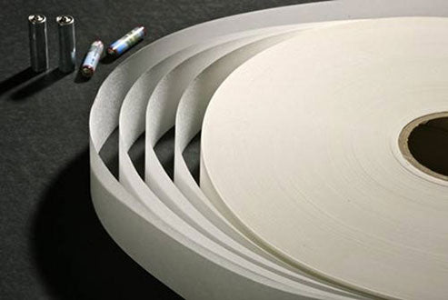
Polyethylene and polypropylene separators have the defect of poor affinity for electrolytes. In this regard, it needs to be modified, such as grafting hydrophilic monomers on the surface of polyethylene and polypropylene microporous membranes or changing the organic solvent in the electrolyte. The polyolefin membranes currently used (as shown in Figure 1) are all thinner (<30μm). Other materials are used as lithium-ion battery separators. For example, some studies have found that cellulose composite membrane materials have good lithium ion conductivity and good mechanical strength, and are also used as lithium-ion battery separator materials.

Figure 1-Polyolefin separator for lithium ion batteries
The preparation methods of lithium-ion battery separators mainly include melt stretching (MSCS), also known as stretch pore-making method, or dry method and thermally induced phase separation (TIPS) or wet method. Because the MSCS method does not include any phase separation process, the process is relatively simple and there is no pollution in the production process. At present, most of the world uses this method for production, such as Japan's Ube, Mitsubishi, Tonen and Celanese in the United States. The process of the TIPS method is more complicated than that of the MSCS method, and the diluent needs to be added and removed. Therefore, the production cost is relatively high and may cause secondary pollution. Currently, Japan's Asahi Kasei, America's Akzo and 3M companies use this method to produce diaphragms in the world.
In lithium batteries, the basic function of the separator is to prevent electron conduction while conducting ions between the positive and negative electrodes.
Polypropylene microporous membranes are usually used in lithium primary batteries; the common separators for lithium ion secondary batteries are polypropylene and polyethylene microporous membranes, which have good chemical and electrochemical stability in secondary batteries.
In summary, the requirements for separator materials for lithium-ion batteries are as follows.
①Thickness. Generally used lithium-ion batteries use thinner separators (<25μm); while the separators used in electric vehicles and hybrid vehicles are thicker (about 40μm). Generally speaking, the thicker the separator, the greater its mechanical strength, and the less likely it is to puncture during battery assembly. However, the same type of battery, such as a cylindrical battery, has less active materials that can be added to it; on the contrary, the use of a thinner diaphragm takes up less space, and more active materials are added, which can increase the capacity and specific capacity of the battery at the same time (due to the increased interface area), and the thinner diaphragm also has lower impedance.
②Permeability. The diaphragm has little effect on the electrochemical performance of the battery. For example, the presence of the diaphragm can increase the resistance of the electrolyte by 6 to 7 orders of magnitude, but it has little effect on the performance of the battery. The impedance coefficient produced by the electrolyte flowing through the effective pores of the diaphragm is usually distinguished from the electrolyte resistance impedance coefficient. The former is called MacMullin coefficient. In commercial batteries, the MacMullin coefficient is generally 10~12.
③ Air permeability. For a given form of diaphragm material, its air permeability is proportional to its electrical resistance. The separator for lithium ion batteries should have good electrical properties and low air permeability.
④Porosity rate. The porosity and permeability are closely related, and the porosity of the lithium ion battery separator is about 40%. For lithium-ion batteries, it is very important to control the porosity of the separator. The standard porosity is an integral part of the diaphragm standard.
The high porosity and uniform pore size distribution will not hinder the flow of ions, while the uneven pore size distribution will cause uneven current density, thereby affecting the activity of the working electrode. Because some parts of the electrode are inconsistent with other parts of the work load, the battery core will eventually be damaged more quickly.
The porosity of the diaphragm is defined as the ratio of the void volume of the diaphragm to the apparent geometric volume of the diaphragm. The density of the material, the mass of the matrix and the size of the material are usually used to calculate the porosity of the diaphragm. The formula is as follows:
Pore volume ratio = (1-sample mass / sample volume / polymer density) × 100%
The standard test method is as follows: first weigh the mass of the pure diaphragm, then drop a liquid (such as hexadecane) into the diaphragm, then weigh its mass, and estimate the volume occupied by hexadecane and the porosity in the diaphragm in turn.
Porosity = volume occupied by hexadecane / (volume of diaphragm + volume occupied by hexadecane) × 100%
⑤ Wetting property. The diaphragm should have the characteristics of rapid and complete wetting in the battery electrolyte.
⑥ Absorb and retain electrolyte. In lithium-ion batteries, the separator can mechanically absorb and retain the electrolyte in the battery and cause no swelling. Because the absorption of electrolyte is required for ion transmission.
⑦Chemical stability. The diaphragm can exist stably in the battery for a long time, and is chemically inert to both strong oxidation and strong reduction environments. It will not degrade under the above conditions, will not lose mechanical strength, and will not produce impurities that affect battery performance. At a temperature as high as 75°C, the separator should be able to withstand the oxidation of the strong oxidizing positive electrode and the corrosion of the strong corrosive electrolyte. The stronger the oxidation resistance, the longer the life of the separator in the battery. Polyolefin separators (such as polypropylene, polyethylene, etc.) are resistant to most chemical substances, have good mechanical properties and can be used in the medium temperature range. Polyolefin separators are an ideal choice for commercial lithium-ion battery separators. In contrast, the polypropylene film has better oxidation resistance in contact with lithium-ion battery cathode materials. Therefore, in the three-layer membrane (PP/PE/PP), polypropylene (PP) is placed on the outer layer and polyethylene (PE) is placed on the inner layer, which increases the oxidation resistance of the membrane.
⑧ Spatial stability. When the separator is removed, the edges should be flat and not curled to prevent the battery assembly from becoming complicated. The diaphragm cannot shrink when it is immersed in the electrolyte, and the cell cannot have a negative impact on the structure of the diaphragm hole when it is wound.
⑨ Puncture strength. The separator used in the wound battery has high requirements for its puncture strength, so as to prevent the electrode material from penetrating the separator. If part of the electrode material penetrates the separator, a short circuit will occur and the battery will be useless.
The separator used in lithium ion batteries requires higher puncture strength than the separator used in lithium primary batteries.
⑩Mechanical strength. The sensitivity of the diaphragm to the penetration of electrode material particles is characterized by its mechanical strength. During the winding process of the battery core, a great mechanical stress will be generated between the positive electrode and the negative electrode interface of the separator, and some loose particles may forcibly penetrate the separator, causing the battery to short-circuit.
⑪ Thermal stability. The moisture in lithium-ion batteries is harmful, so the cells are usually dried under vacuum drying conditions at 80°C. Therefore, under this condition, the diaphragm cannot shrink significantly. Each battery manufacturer has its own unique drying process. The requirements for lithium ion secondary battery separators are: drying at 90°C for 60 minutes, the transverse and longitudinal shrinkage of the separator should be less than 5%.
⑫Aperture. For lithium-ion battery separators, since the most critical requirement is not to allow lithium dendrites to pass through, separators with submicron pore diameters are suitable for lithium-ion batteries.
The diaphragm is required to have a uniform pore size distribution to prevent the loss of electrical properties due to uneven current density. The sub-micron diaphragm pore size can prevent short circuits between the positive and negative electrodes in the lithium-ion battery, especially when the diaphragm develops to a thickness of 25 μm or less, the short circuit problem is more likely to occur. These issues will receive more and more attention as battery manufacturers continue to adopt thin diaphragms and increase battery capacity. The pore structure is affected by the composition of the polymer and the stretching conditions, such as stretching temperature, speed, and ratio. In the wet process, the diaphragm is stretched after being refined. The diaphragm produced by this process has a larger pore size (0.24~0.34μm), and the pore size distribution is wider than the diaphragm produced by the process of stretching and then refining (0.1~0.13μm).
The testing of lithium-ion battery separators and the control of micropore characteristics are very important. The mercury pore size tester is usually used to characterize the diaphragm in the form of porosity percentage, which also indicates its pore size and pore size distribution. According to this method, mercury can be injected into the pores under pressure, and the size and volume of the pores of the material can be determined by determining the amount of mercury. Mercury is non-wetting to most materials, and the applied external force must overcome the surface tension to enter the hole.
Hydrophobic separators (such as polyolefins) can be characterized by solvent (non-mercury pore size tester) technology, which is a very useful characterization method for polyolefin separators for lithium-ion batteries. The pore volume, surface area, median pore size data and pore size distribution can be obtained through the pore size tester. During the experiment, the sample is placed in the instrument, and as the pressure increases, the amount of water injected varies with different pore volumes. Therefore, pressure applied to a diaphragm with a certain pore size distribution can obtain a one-to-one volume or pore size corresponding to the pressure. Suppose the pressure required to inject water into a micropore with a certain pore size is P, so that the pore size D can be calculated as follows:

Where:
D——Assuming the hole is cylindrical aperture;
P——Differential pressure;
γ——Surface tension of non-wetting liquid;
θ——The contact angle of water.
The pores of the diaphragm are usually not spherical with a certain diameter, but have a variety of shapes and sizes. Therefore, any statement about the pore size is based on the above assumptions.
Scanning electron microscopy (SEM) is also used to characterize the morphology of the diaphragm. Figure 2 shows the SEM image of the commercial diaphragm (PE).

Figure 2 - SEM image of a single-layer Celgard separator (PE) in a lithium-ion battery
Figure 2 shows the SEM image of Celgard 2730. It can be seen that the pore size distribution is very uniform, which is suitable for high-magnification equipment. Figure 3 is the surface and cross-sectional SEM image of Celgard 2325, the surface can only see the pores of PP, and the pores in PE can be seen in the cross-sectional SEM image; it can be clearly seen from the cross-sectional SEM image that the thickness of the three-layer diaphragm is the same. Figure 4 is the SEM image of the membrane material prepared by the wet process. It can be seen that the structure of all these membranes is very similar, and the pore size of the Hipore-1 membrane [Figure 4(b)] is significantly larger than other membranes.

Figure 2-SEM image of Celgard 2325 (PP/PE/PP) separator for lithium-ion batteries: (a) Surface SEM; (b) Cross-section SEM

Figure 4-SEM image of the diaphragm of a lithium-ion battery prepared by a wet method: (a) Setela (Tonen); (b) Hipore-1 (Asahi); (c) Hipore-2 (Asahi); (d) Teklon (Entek)
⑬ Tensile strength. The diaphragm is wound with the electrode under tension. In order to ensure that its width does not shrink, the length of the diaphragm cannot be significantly increased during the stretching process. "Young's modulus" is the main parameter in tensile strength. Since the measurement of "Young's modulus" is difficult, the residual deformation yield of 2% is used as an estimation standard.
⑭Distortion rate. Unfold a diaphragm. Ideally it is straight and will not bend or twist. However, in practical applications, a twisted diaphragm will be encountered. If the twist is too severe, the equipment between the electrode material and the diaphragm will cause inaccuracies. The degree of distortion of the diaphragm can be measured by placing it on a horizontal table with a ruler. For the diaphragm of a lithium ion battery, the degree of distortion should be less than 0.2mm/m.
⑮Interrupt the current. In the lithium ion battery separator, it is also possible to design a protective band for the battery in the case of overcharge or short circuit, that is, the resistance of the separator will suddenly increase at about 130°C, thereby preventing lithium ions from being transferred between the electrodes. When the diaphragm is above 130°C, the safer the protective band, the better the function of the diaphragm will be maintained. When the diaphragm ruptures, there may be direct contact between the electrodes, a reaction occurs, and a huge amount of heat is released. The interrupting current behavior of the diaphragm can be characterized by heating the diaphragm to a high temperature and then measuring its resistance.
For limiting temperature and preventing battery short circuit, interrupting current temperature is a very useful and effective mechanism. The interrupting current temperature is usually selected near the melting point of the polymer membrane. At this time, the pores of the diaphragm collapse, forming a non-porous insulating layer between the electrodes. At this temperature, the resistance of the battery also increases sharply, and the passage of current in the battery is blocked, thereby preventing further electrochemical reactions in the battery. Therefore, the battery reaction can be interrupted before the battery explodes.
The performance of PE battery separator to block current is determined by its molecular weight, density score and reaction mechanism. The nature of the material and the manufacturing process need to be exquisite, so that the interrupted current can be fed back instantly and comprehensively. Optimizing the design within the allowable temperature range and without affecting the mechanical properties of the material is very easy for the three-layer diaphragm made by Celgard. Because in the Celgard diaphragm, there is one layer used to interrupt the feedback of the current, and the other two layers only require its mechanical properties, the diaphragm laminated by the PP/PE/PP three layers is very meaningful to prevent the thermal runaway of the battery. The interruption current temperature of 130°C is sufficient to prevent thermal runaway and overheating of lithium-ion batteries. If it does not negatively affect the mechanical properties of the separator and the high temperature performance of the battery, a lower interruption current temperature is also feasible.
The interrupting current property of the diaphragm is determined by measuring the change of the diaphragm resistance as the temperature rises linearly. Figure 5 shows the measurement curve of the Celgard 2325 diaphragm. The heating rate is 60°C/min and the diaphragm resistance is measured at 1kHz. It can be seen from Figure 5 that near the melting point of the separator (130°C), the resistance of the separator rises sharply. This is caused by the collapse of the separator's pores near the melting point. In order to prevent thermal runaway of the battery, the resistance of the separator needs to be increased by more than 1000 times. As the temperature increases, the resistance has a downward trend, which is caused by polymer aggregation causing the membrane to shift or the electrode active material penetrates the membrane. This phenomenon is commonly referred to as the loss of "softening integrity".

Figure 5 - Celgard 2325 (PPPEPP) diaphragm internal resistance (1kHz) change curve with temperature (heating rate is 60℃min)
The interrupting current temperature of the diaphragm material is determined by its melting point, and the diaphragm that reaches the melting point will form a non-porous film between the positive and negative electrodes. The DSC (Differential Scanning Calorimetry) diagram of the diaphragm shown in Figure 6 illustrates this point.

Figure 6 - DSC chart of Celgard 2730 (PE), 2400 (PP) and 2325 (PPPEPP)
It can be seen from Figure 2-20 that the melting points of Celgard 2730, 2400 and 2325 are 135°C, 165°C and 135/165°C, respectively. Whether it is a thin membrane (<20μm) or a thick membrane, their interrupting current behavior is similar. of.
⑯ High temperature stability performance Under high temperature conditions, the diaphragm is required to prevent the electrodes from contacting each other. The high temperature stability of the diaphragm is characterized by thermomechanical analysis (TMA). The so-called TMA is to measure the ratio of diaphragm growth to temperature under certain load conditions.
⑰ Electrode interface The diaphragm and electrode should provide a better interface for electrolyte flow.
In addition to the above requirements, the diaphragm should also overcome the following defects: pinholes, wrinkles, colloids, dirt, etc. All the above-mentioned characteristics of the separator should be optimized before the application and equipment of lithium-ion batteries.


