

Main content:
There are many classification principles for inverters for photovoltaic power generation systems. For example, according to the number of phases of the output AC voltage of the inverters for photovoltaic power generation systems, it can be divided into single-phase inverters for photovoltaic power generation systems and three-phase inverters for photovoltaic power generation systems. Inverter; according to the different types of semiconductor devices used in inverters for photovoltaic power generation systems, it can be divided into transistor inverters for photovoltaic power generation systems, thyristor inverters for photovoltaic power generation systems, and turn-off thyristor photovoltaic power generation systems. Inverters, etc.; according to the different circuit principles of inverters for photovoltaic power generation systems, they can also be divided into self-excited oscillation inverters for photovoltaic power generation systems, stepped wave superimposed inverters for photovoltaic power generation systems, and pulse width modulation photovoltaic power generation systems. Inverters for photovoltaic power generation systems, etc. In order to facilitate the selection of inverters for photovoltaic power generation, here we first classify the different output AC voltage waveforms of the inverters, and briefly describe the characteristics of inverters with different output waveforms.
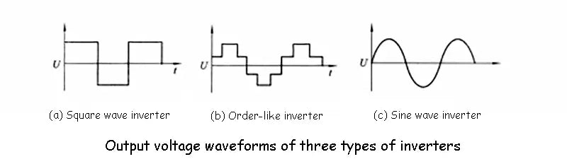
1. Square wave inverter in inverters for photovoltaic power generation system
The AC voltage waveform output by the square wave inverter in the inverters for photovoltaic power generation system is a square wave, as shown in the following figure (a). The number of power switches used is very small, and the design power is generally between tens of watts to hundreds of watts. The advantages of the square wave inverter are: cheap and easy maintenance; the disadvantage is: because the square wave voltage contains a large number of high-order harmonics, additional losses will be generated in the electrical devices that use the transformer as the load. Communication equipment also interferes. In addition, some of these inverters have insufficient voltage regulation range, insufficient protection function, and relatively large noise.
2. Step inverters in inverters for photovoltaic power generation systems
The AC voltage waveform output by the ladder inverter in the inverters for photovoltaic power generation system is a ladder wave, as shown in the figure (b) below. There are also many different circuits for the inverter to realize the step wave output, and the number of steps of the output waveform is also different. The advantage of the ladder inverter is that the output waveform is significantly improved compared with the square wave, and the high-order harmonic content is reduced. When the ladder reaches more than 17, the output waveform can achieve a quasi-sine wave. When the transformerless output is used, the overall efficiency is very high. The disadvantage is that there are many power switch tubes used in the ladder wave superposition circuit, and some of the circuit forms also require multiple sets of DC power input. This brings trouble to the grouping and receiving of the solar cell array and the balanced charging of the storage battery. In addition, there is still some high frequency interference from the step wave voltage to radios and some communication equipment.
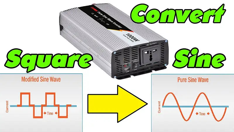
3. Sine wave inverters in inverters for photovoltaic power generation systems
The AC voltage waveform output by the sine wave inverter in the inverters for photovoltaic power generation system is a sine wave. As shown in the figure (c) below, the sine wave inverter has good comprehensive technical performance and perfect function, but the circuit is complicated. The advantages of the sine wave inverter are: good output waveform, low distortion, no interference to radio and communication equipment, and low noise; the disadvantages are: the circuit is relatively complex, the maintenance technology is required to be high, and the price is expensive.
The above three classification methods of inverters for photovoltaic power generation systems are only for reference by photovoltaic power generation system developers and users when identifying and selecting inverters for photovoltaic power generation systems. In fact, inverters for photovoltaic power generation systems with the same waveform are still very different in terms of circuit principles, use periods and control methods. In addition, from the perspective of the development status and prospects of high-efficiency inverter power supply, it is necessary to focus on the problem that inverter power supply can be divided into power frequency cnversion and high frequency conversion according to the conversion method. At present, most of the inverter power supplies on the market are power frequency conversion. It uses discrete devices or integrated blocks to generate a 50Hz square wave signal, and then uses this signal to drive the power switch tube, and uses a power frequency booster to generate 220V alternating current. This kind of inverter power supply has a simple structure and reliable operation, but due to the defects of the circuit structure itself, it is not suitable for driving inductive loads, such as refrigerators, electric fans, water mercury, fluorescent lamps, etc. In addition, this kind of inverter power supply is bulky, bulky and expensive due to the use of a power frequency transformer.
In the early 1970s, the application of 20 kHz PWM switching power supply caused the so-called "20 kHz power supply technology revolution" in the world. This idea about the inverter power conversion method was immediately used in the inverter power supply system at that time. Because the power devices at that time were expensive and the damage was great, the research on high frequency and high efficiency inverter power supply has been stagnant. After the 1980s, with the maturity of the power FET technology and the improvement of the quality of magnetic materials, the high-frequency conversion inverter power supply came to the market.
The high-frequency conversion inverter power supply converts low-voltage DC into low-voltage AC by increasing the DC-DC conversion frequency, and then rectifies it into high-voltage DC after boosting by a pulse transformer. Since PWM technology is used in DC-DC conversion, a stable DC voltage can be obtained, and the load can be directly driven by AC energy-saving lamps, incandescent lamps, and color TV sets.
If the quasi-sine transformation or sine transformation is performed on the high voltage direct current, 220V, 50Hz sine wave alternating current can be obtained. This kind of inverters for photovoltaic power generation system adopts high frequency conversion (mostly 20kHz~200kHz), so it is small in size and light in weight; due to the use of secondary width adjustment and secondary voltage regulation technology, the output voltage is very stable, With strong load capacity and high performance and price, it is the first choice in the current renewable energy power generation system. With the development of resonant switching power supply, the idea of resonant transformation is also used in the inverter power supply system, which constitutes a resonant high-efficiency inverter power supply. This inverter power supply adopts zero-voltage or zero-current switching technology in DC-DC conversion, so the switching loss can be basically eliminated. Even when the switching frequency exceeds 1MHz, the efficiency of the power supply will not be significantly reduced. Experiments have shown that the loss of the resonant conversion can be reduced by 30% to 40% compared to the loss of the non-resonant conversion under the same operating frequency. Recently, the operating frequency of resonant power supply can reach 500kHz to 1MHz.
In addition, it is worth noting that the research of inverter power supply is developing in the direction of modularization, that is, different voltage and waveform conversion systems can be formed by using different combinations of modules.
Due to the high cost of electrical energy provided by photovoltaic power generation systems, it is very important to develop efficient and reliable inverters for photovoltaic power generation systems. To improve the efficiency of inverters for photovoltaic power generation systems, it is necessary to reduce their losses. Losses in inverter power supplies can generally be divided into two categories: conduction losses and switching losses. The conduction loss is because the device has a certain on-resistance Rds, so a certain amount of power consumption will be generated when a current flows. During the turn-on and turn-off process of the device, the device will also generate a large loss, which is called switching loss. Switching losses can be divided into turn-on losses, turn-off losses, and capacitor discharge losses. Modern power supply theory points out that to reduce these losses, it is necessary to implement zero-voltage or zero-current conversion of the power switch, that is, to use a resonant conversion structure.
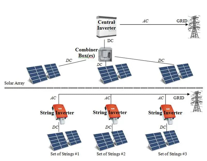
Modularity has the advantages of simple debugging and flexible configuration. Therefore, in the process of developing high-efficiency inverters for photovoltaic power generation systems, the modular structure shown in the figure below can be used.
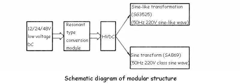
Users can arbitrarily match various modules according to the actual power requirements to form a high-efficiency inverter power supply that requires input or output.
Read more: The basic working principle and circuit system of the inverter


