Main content:
1. Introduction to Inverter
As mentioned above, the so-called inverter is a kind of power conversion device that converts DC power into AC power to supply the load. It happens to be the reverse conversion function device of the rectifier device, so it is called an inverter. In photovoltaic power generation systems, solar panels generate direct current under sunlight. However, systems powered by direct current have great limitations. For example, most household appliances such as fluorescent lamps, televisions, refrigerators, and electric fans cannot be directly powered by DC power, and the same is true for most power machinery. In addition, when the power supply system needs to increase or decrease the voltage, the AC system only needs to add an inverter, while the step-up and step-down technology and devices in the DC system are much more complicated. Therefore, except for special users, inverters are required in photovoltaic power generation systems. The inverter is also generally equipped with automatic frequency stabilization and voltage stabilization function, which can ensure the power supply quality of the photovoltaic power generation system. Therefore, the inverter has become an indispensable and important equipment in the photovoltaic power generation system.
At present, the development and production of power semiconductor devices has developed by leaps and bounds. Power semiconductor devices are the basic components of high-efficiency inverters. At present, they are developing towards modularization, rapidity, high frequency, large capacity and intelligence.
Inverters belong to the category of power electronics. Power electronics is a fringe science between the three major fields of electrical engineering, power, electronics and control. The inverter function requires the inverter to work according to a repeated switching mode, which is the category of numerical control electronics; and the signal of the switching action requires the inverter to be continuous, which is the object of analog control research. Therefore, the research of inverters is based on the knowledge of power electronics and control, which is exactly the content of power electronics.
2. The basic principle of inverter
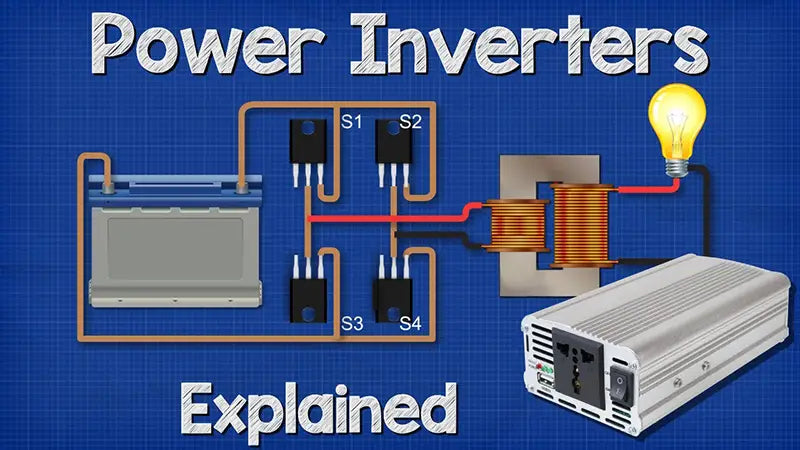
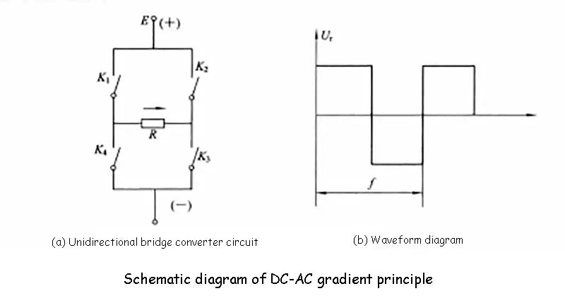
There are many types of inverters, and their working principles and processes are different, but the most basic inverter process is the same. The following takes the most basic inverter-single-phase bridge inverter circuit as an example to describe the "inversion" process of the inverter in detail. The single-phase bridge inverter circuit is shown in the figure (a) below, and the waveform of the voltage is shown in the figure (b) below. The input DC voltage is E and R represents the pure resistive load of the inverter. When the switches K1 and K3 are turned on, the current flows through K1, R and K2, and the voltage polarity on the load is left positive and right negative; when the switches K1 and K3 are turned off, when K2 and K4 are turned on, the current flows through K2, R, K4, the voltage polarity on the load is reversed. If the two sets of switches K1 and K3 , K2 and K4 are switched alternately at the frequency f, the load R can obtain the alternating voltage U of the frequency f, and its waveform is shown in the following figure (b). The waveform is a square wave with a period of T=1/f.
The switches K1, K2, K3, and K4 in the circuit (a) below are actually an ideal model of various semiconductor switching devices. Power switching devices commonly used in inverter circuits include power transistors, power field effect transistors, turn-off thyristors and fast thyristors. In recent years, insulated gate bipolar transistors with lower power consumption and faster switching speed have been developed.
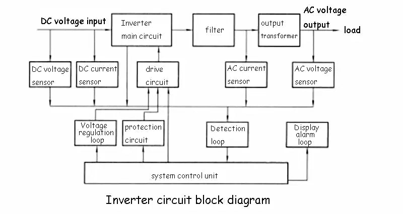
In fact, to form a practical inverter, many important functional circuits and auxiliary circuits need to be added. The output is a sine wave voltage, and the block diagram of the inverter circuit with a certain protection function is shown in the figure below. The working process of the inverter is briefly described as follows: the DC power sent by the solar cell square array (or battery) enters the main circuit of the inverter, is converted into an AC square wave by the inverter, and then becomes a sine wave voltage after being filtered by a filter. Finally, it is boosted by the transformer and sent to the electrical load. The switching process of the power switch tube in the main circuit of the inverter is controlled by the system control unit through the drive circuit. The working state and working parameters of each part of the inverter circuit are transformed into identifiable electrical signals through sensors with different functions, and then sent to the system control unit through the detection loop for comparison, analysis and processing. According to the judgment result, the system control unit controls the working conditions of each circuit of the inverter. For example, the output voltage value of the inverter can be adjusted through a voltage regulation loop. When the detection circuit sends short-circuit information, the system control unit immediately turns off the switch tube of the main circuit of the inverter through the protection circuit, so as to protect the inverter. The main status information and fault conditions of the inverter work can be sent to the display and alarm circuit through the system control unit. According to the power size and function of the inverter, the system control unit in the figure below can be a simple logic circuit or a professional chip composed of a single component, and a complex one can be a single-chip microprocessor or a 16-bit microprocessor. In addition, the following figure shows the typical circuit system principle of the inverter. The actual inverter circuit system can be much simpler or more complicated than the one shown in the figure below. It is best to explain that, An inverter with perfect power and good performance, in addition to having all the functional circuits shown in the figure below, also has a secondary power supply (ie, the power supply for the control and detection circuit). The power supply is responsible for providing different levels of low-voltage working power to all the power-consuming parts, components, instruments, etc. of the inverter.