

As one of the core components of the photovoltaic system, the inverter not only has the function of DC-AC conversion, but also maximizes the performance of solar cells and the system fault protection, which directly affects the power generation efficiency of the solar system.
Inverters such as 2000w inverter and 3000w inverter are widely used in many scenarios of life and work, but you may wonder, what makes them so powerful? What is the working principle of inverter? This article will give you the answer.
Main content:
1. Basic working principle of inverter
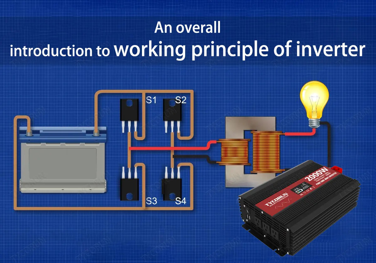
An inverter is a device that converts DC power into AC power. The working principle of inverter is to use the switching characteristics of semiconductor devices (such as field effect transistors or thyristors, etc.) to control the power supply voltage and current through rapid switching, thereby converting DC power into alternating current of corresponding frequency and voltage.
Specifically, when the input DC power passes through the semiconductor device in the inverter, it is divided into a series of pulse signals, which are filtered and adjusted to produce AC power with the same frequency, amplitude and waveform as the desired output. Inverters are widely used in many fields such as solar power generation, wind power generation, household appliances, and UPS.
2. Inverter circuit structure
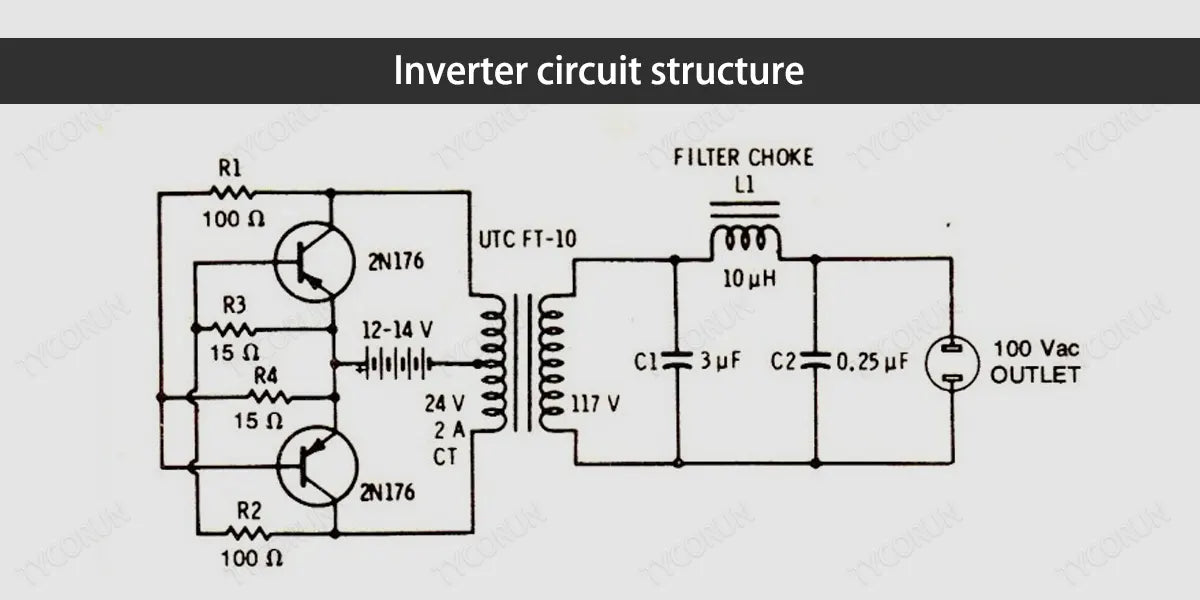
In the working principle of inverter, the internal circuit structure of the inverter is divided into two parts, namely the control circuit and the power circuit. The control circuit mainly implements signal conditioning and control of the inverter, including controlling the switching state of the thyristor or field effect transistor, generating high-frequency drive pulse signals, and providing protection.
Control circuits usually consist of microprocessors or complex circuit boards. The power circuit is the core component of the inverter, which converts DC power into AC output, including rectifier circuit, filter circuit and inverter output circuit.
The rectifier circuit converts the input alternating current into direct current, the filter circuit smoothes the rectified direct current, and the inverter output circuit uses semiconductor devices to convert the direct current into alternating current with the required voltage, frequency, and waveform.
The internal circuit structure of the inverter is complex, which affects the working principle of inverter. Scientific and precise design and manufacturing processes are required to ensure its performance and safety.
3. Full-bridge inverter
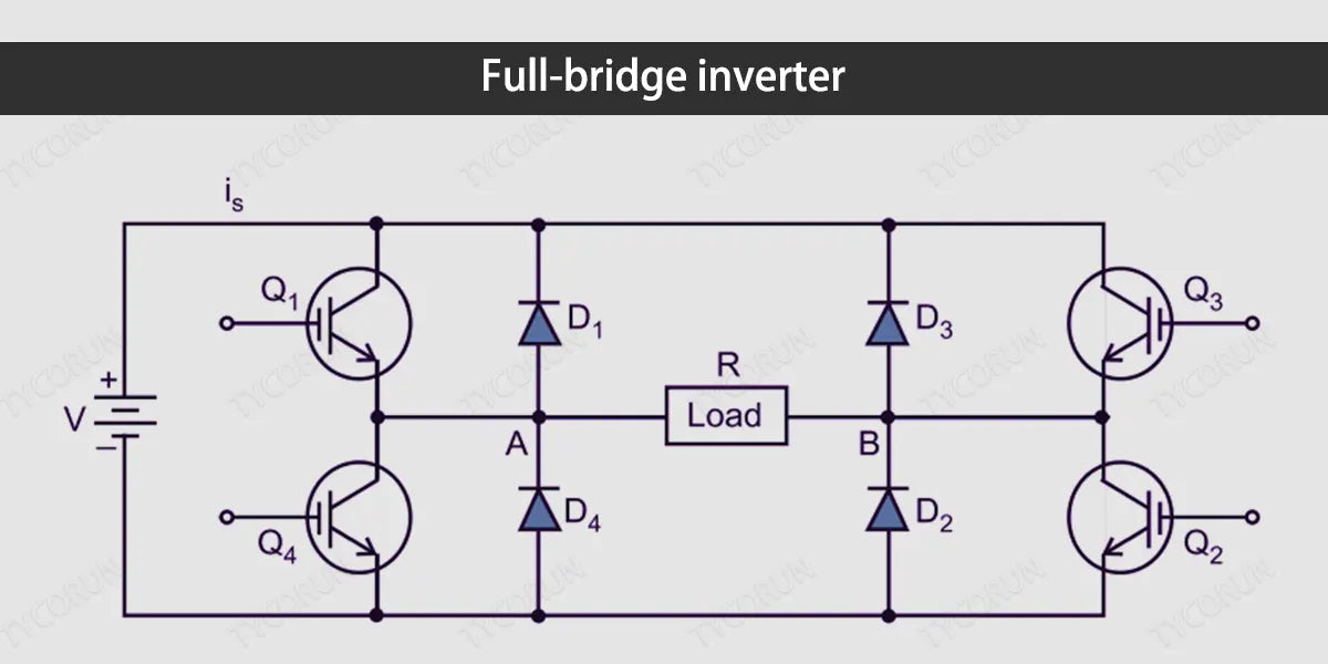
The full-bridge inverter is a common inverter circuit that is widely used in industry, aviation, marine and other fields. Its basic role in the working principle of inverter is to alternately conduct the DC power supply through four switching tubes (often using IGBT or MOSFET) to achieve AC output.
Specifically, the four switch tubes in the full-bridge inverter can be divided into two groups: the upper arm and the lower arm. The upper bridge arm is composed of two switching tubes and a midpoint, and the lower bridge arm is also composed of two switching tubes and a midpoint.
In each half cycle, the two switches on one bridge arm are turned on and the two switches on the other bridge arm are turned off, which causes the power supply DC voltage to be connected to the output terminal L1 and L2 in turn at the midpoint, thus forming the positive and negative half cycles of communication.
In the control of the full-bridge inverter, precise switching control of the four switching tubes is required to ensure that they can switch and conduct correctly in different states. In addition, auxiliary components such as filter capacitors and inductors are also required to smooth the output waveform and reduce transient and noise interference.
In short, the full-bridge inverter has the advantages of simplicity, reliability, and stable output, and is widely used in situations where high performance is required.
4. Structure and working principle of inverter PWM
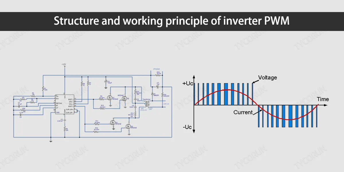
PWM (Pulse Width Modulation) control is one of the main control technologies of the inverter. Its basic role in the working principle of inverter is to adjust the frequency and amplitude of the output waveform by controlling the conduction time of the switch tube.
Specifically, PWM control converts DC power into a set of short pulse signals and controls its duty cycle to achieve high-quality AC output. In the inverter, the comparative PWM control method is used, that is, the input signal is compared with a Gaussian wave to generate an error signal, and the control signal of the inverter switch tube is generated based on this error signal to achieve high-frequency modulation and produce the desired waveform.
During specific implementation, the opening and closing of each switch tube can be completed through the calculation of the controller and the control of the PWM chip. The structure of inverter PWM control mainly includes comparator, error amplifier, low-pass filter and PWM controller.
The comparator is mainly responsible for generating an error signal and sending it to the error amplifier; the error amplifier amplifies the error signal and outputs a PWM control signal; the PWM controller transmits the PWM signal to switching tubes such as IGBT or MOSFET to control the output waveform .
In short, PWM control is an important technology for working principle of inverter to achieve high-quality AC output. It has the characteristics of high precision and good stability, and has been widely used in fields such as solar power generation and electric vehicles, including golf cart battery and trolling motor battery.
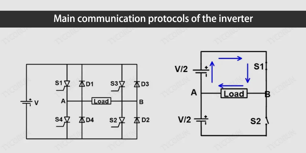
5. Main communication protocols of the inverter
The main communication protocols of the inverter are as follows:
- Modbus protocol: Modbus is a common serial communication protocol that can realize data exchange between different devices. In the inverter, the Modbus protocol can be used to achieve remote monitoring and control, including real-time monitoring of the inverter output power, voltage, current and other parameters, and adjustment of the output waveform and frequency.
- CAN bus protocol: The CAN bus protocol is a network protocol based on the wide area network (WAN), which has the characteristics of high reliability, high speed, and high system integration. In the inverter, the CAN bus protocol can be used to realize data exchange and control between multiple inverters, as well as communication with other devices.
- Ethernet protocol: Ethernet is a standard network protocol based on local area network (LAN). Its characteristics of fast data transmission rate, high flexibility and support for multiple applications allow the inverter to communicate externally through the Internet and use Web-based interface to set the inverter parameters.
- Zigbee wireless protocol: Zigbee is a low-power wireless protocol that can establish a stable and secure network in homes, offices and other environments, and supports direct communication between target devices. In the inverter, the Zigbee wireless protocol can be used to realize wireless communication between the inverter and other devices, expanding the scope of monitoring and control.
In short, different communication protocols are used in the inverter to quickly and accurately realize data exchange and remote control, providing users with more efficient and convenient services.
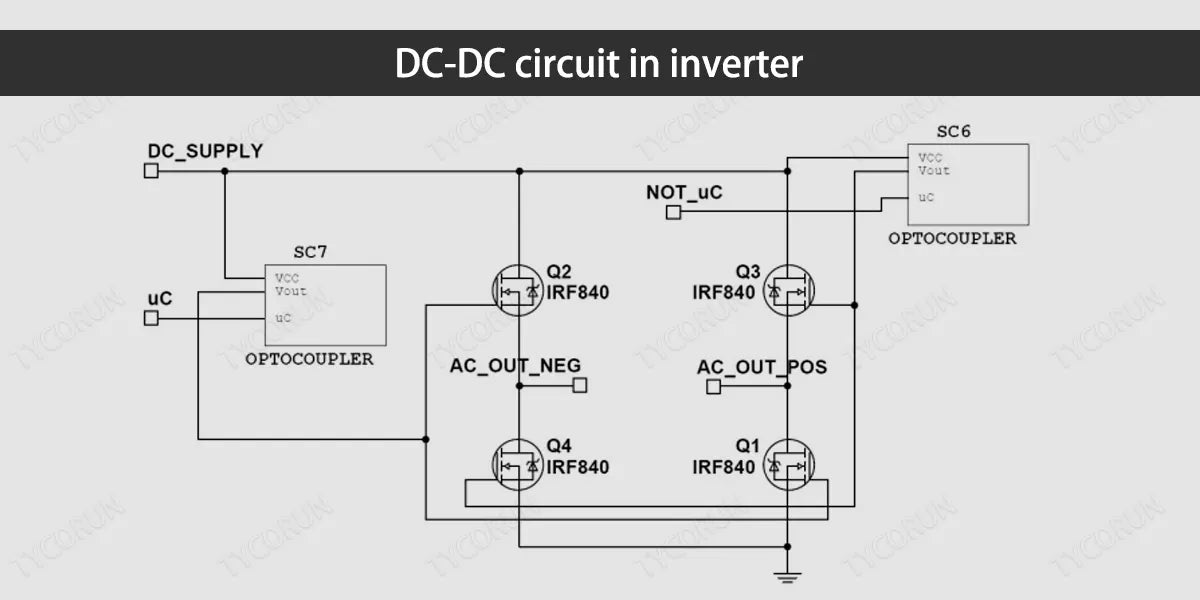
6. DC-DC circuit in inverter
The DC-DC in the inverter refers to the converter from direct current to direct current. The DC-DC circuit is not common to all inverters, only some inverters have it. In the inverter, DC-DC is mainly used to regulate and convert the input voltage to meet the power supply needs of the inverter and its output load.
Specifically, DC-DC can achieve the following functions in the working principle of inverter:
- Voltage rise and fall: When the input voltage of the inverter is lower than the output voltage, DC-DC can increase the voltage to ensure the normal operation of the inverter. On the contrary, when the input voltage is higher than the output voltage, DC-DC can reduce the voltage to reduce the power loss of the inverter.
- Current control: DC-DC can achieve precise control of the output current by changing parameters such as switching frequency and duty cycle according to the needs of the output load to prevent circuit overload or power supply fluctuations from affecting the output load.
- Energy storage: DC-DC can also realize energy storage and management. For example, by using it in conjunction with a battery pack like lfp battery, it can store and reuse electricity generated by renewable energy sources such as photovoltaic or wind power.
- Safety protection: Under abnormal conditions such as inverter overload, short circuit, undervoltage, etc., DC-DC can immediately cut off the input power to avoid further damage to the inverter and output load, which affects how inverter works.
In short, the DC-DC in the inverter is an important power conversion module, which can achieve precise control and management of the input power and provide stable and reliable power for the inverter and its load.
Tycorun 12V inverters guarantee reliable pure sine wave output with a lower price than other competitors, please check 3000w power inverter 12v, pure sine inverter 2000w, inverter pure sine wave 1000w, 500 watt pure sine wave inverter
Related posts: 12 volt 100ah deep cycle lithium battery, Best solar inverter brands, Inverter batteries near me


