


main content:
Carbon materials are mainly divided into graphite-based carbon materials and amorphous carbon materials. They are all composed of graphite microcrystals, but their crystallinity is different, and other structural parameters are different, so their physical and chemical properties And electrochemical performance presents their own characteristics; carbon crystals also include diamond and fullerene, but they only exist as allotropes of carbon, so they cannot be used in lithium-ion batteries. Other carbon materials also include carbon nanotubes, nanoporous carbon anode materials and nano-doped carbon materials.
Graphite carbon materials mainly refer to various graphite and graphitized carbon materials, including natural graphite, artificial graphite and various modified materials of graphite.
The structure of carbon materials determines the properties of carbon materials. For general carbon materials, its structure includes two aspects: crystal structure and macro-texture. However, for anode materials used as lithium-ion batteries, the surface structure and structural defects of carbon materials It has a great influence on the performance of the electrode.
(1) Graphite crystal structure
Graphite is an allotrope of carbon, and its crystals have a layered structure. In each layer, the carbon atoms form three coplanar σ bonds with the other three adjacent carbon atoms in a sp² hybrid manner, and these coplanar carbon atoms are there. A large six-ring network structure is formed under the action of the σ bond and connected into a sheet structure to form a two-dimensional graphite layer. The electrons of each carbon atom that are not involved in the hybridization form a large π conjugated system on both sides of the plane; The layers are combined with the intermolecular force-Van der Waals force. Because the carbon atoms in the same layer are bonded by a strong covalent bond, the melting point of graphite is very high (3850°C), but because the intermolecular force between the layers is non-bonding force, it is weaker than chemical bonds and easy to slide, which makes the hardness of graphite Very small and lubricating. At the same time, due to the resonance of electrons in the large π conjugated system, π electrons are easy to flow and have good conductivity. Figure 1 is a schematic diagram of the structure of graphite crystals.
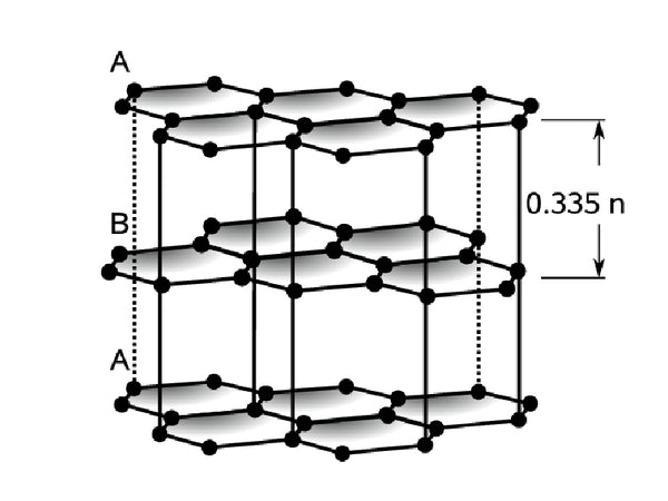
Figure 1 Schematic diagram of graphite crystal structure
In fact, graphite is composed of two crystals, one is a hexagonal structure (2H, a=b=0.2461nm, c=0.6708nm, α=β=90°, γ=120°), and the spatial point group is P63/ mmc, the carbon sublayers are arranged in the ABAB manner; the other is the rhombus structure (3R, a=b=c, a=B=γ≠90°), the spatial point group is R3m, and the carbon atom layers are arranged in the ABCABC manner. Figure 2 shows two crystals of graphite.
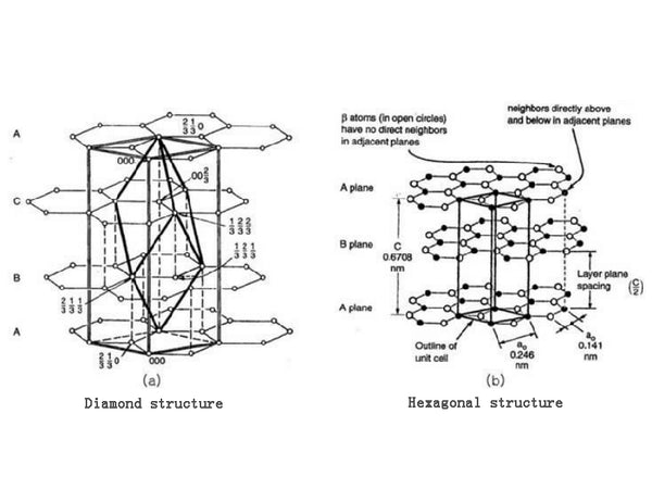
Figure 2 Two crystals of graphite
In graphite crystals, these two structures coexist, but the proportions of each in different materials are different. For example, the proportion of rhombohedrons in natural graphite is generally less than 3% to 4%, while the proportion of rhombohedrons in well-crystallized graphite crystals can be as high as 22%. The content of rhombohedral crystal phase in graphite can be calculated using formula.
ω3R={[101]3R×(15/12)}/{([101]3R×(15/12))+[202]2H}×100%
In the formula, [101]3R and [101]2H are the XRD peak intensities of the [101] plane of the rhombohedral crystal phase and the hexagonal crystal phase, respectively.
Generally speaking, the specific capacity of the rhombohedral phase is higher than that of the hexagonal phase. Adjusting the ratio of these two structures can increase the specific capacity of graphite.
The structural parameters of graphite crystals mainly include La, Lc, d002 and Go. La is the average width of the graphite crystal along the a-axis direction, Lc is the average height of the graphite crystal along the c-axis direction, and d002 is the distance between two adjacent graphite sheets. For ideal The d002 of graphite crystals is 0.3354nm, and for amorphous carbon, d002 is as high as 0.37nm or even higher. The size of La and Lc changes with the degree of graphitization of the carbon material. Generally, the greater the degree of graphitization, the greater the value of La and Lc. These structural parameters of graphite crystals can generally be determined by XRD.
d002(nm)=λ/2θsinθ
La(nm)=0.184λ/βcosθ
Lc(nm)=0.089λ/βcosθ
In the formula, λ, β and θ are the wavelength of the incident X-ray, the half-width of the X-ray diffraction peak and the diffraction angle, respectively.
G=(0.3440-d002)/(0.3440-0.3354)×100%
In the formula, G is the degree of graphitization of different carbon materials. Its value can be calculated by the formulas of Mering and Maire; 0.3440 is the inter-layer spacing of completely ungraphitized carbon, in nm; 0.3354 is the inter-layer spacing of ideal graphite, in nm.
Graphitization degree G reflects two levels of concepts: ①The degree of order in the crystal structure of the carbon material after graphitization. The larger the G value, the closer its structure and properties are to ideal graphite; ②The degree of graphitization of carbon materials, A large G value indicates easy graphitization, and a small G value indicates difficult graphitization.
The graphitization degree G of carbon materials also affects the resistivity: the graphitization degree is high, the lattice size in the layer is large and the lattice defects are small, the layer arrangement tends to be parallel and the layer spacing d002 is small, which reduces the flow of free electrons. Obstructive factors reduce the resistivity.
(2) Microstructure of carbon materials
The microstructure of a carbon material refers to the way that the graphite flakes or graphite crystallites that make up the carbon material are stacked in space. Although different carbon materials are composed of a two-dimensional graphite structure hexagonal mesh surface, in the process of further layering to form crystal grains, the diversity of the aggregate form leads to the diversity of the organizational structure, so it can also be oriented according to its orientation. The way and the degree of orientation divide the carbon materials into two types: an amorphous structure with completely disorderly stacked layers and an oriented structure with a certain set of regularities. Among the highly oriented materials, there are three types of materials: plane orientation, axis orientation and point orientation. Actual carbon materials are composed of one or more of them.
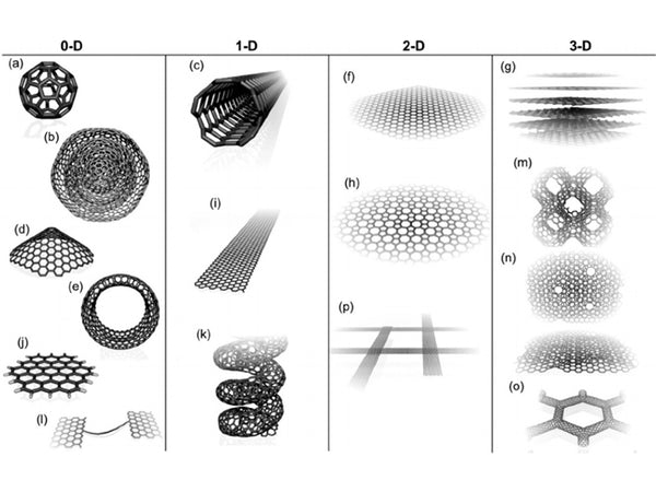
Figure 3 Schematic diagram of the structure of different carbon materials
①Plane-oriented structure refers to the structure of graphite crystallites that are basically parallel. It exists in graphite and petroleum coke. The perfect surface texture is graphite single crystal, and highly oriented pyrolysis graphite (HOPG) is close to the limit; natural flake graphite also has a surface-oriented structure. Many kinds of coke also have this structure, but the mesh surface is small in low temperature treatment, about 1~1.5nm, but it is roughly arranged in parallel. After high temperature treatment, the mesh surface grows and the orientation will be significantly improved, that is, graphite The degree of chemistry has increased.
②Line-oriented structure Axial-oriented structure exists in carbon fiber. There are two typical shaft structures. One type of graphite crystallite is radial, the graphite surface of the crystallite basically passes through the carbon fiber axis, and the graphite surface of the other crystallite is cylindrical. , Coaxial with carbon fiber. Vapor-grown carbon fiber (VGCF) made at around 1100°C is a coaxial cylindrical structure; pitch-based carbon fiber (PCF) can be coaxial cylindrical or radial, which can be controlled by spinning conditions; polyacrylonitrile (PAN)-based carbon fiber The cross-section of the can partially present a structure where concentric circles and radiation are mixed. Radiation structures often produce wedge-shaped defects during high-temperature processing. The low-temperature processed material with an axis-oriented structure also has a small mesh surface. After high-temperature treatment, the mesh surface merges and grows, which can be highly graphitized.
③The point-oriented structure exists in the mesophase carbon microspheres. There are also two typical point structures: one is radial, that is, the microcrystalline graphite passes through the center of the sphere; the other is concentric spherical, that is, the graphite surface of the microcrystalline is concentric. Sphere.
The carbon material with an oriented structure is either graphite or graphitizable carbon. The orientation method is formed in the process of carbonization (low temperature treatment), and further graphitization (high temperature treatment) cannot change it. To change the orientation mode, it often requires a pressure of more than 300 MPa supplemented with very harsh conditions such as high temperature treatment.
(3) Surface structure
The molecules in the surface layer of the substance are different from the surrounding environment of the internal molecules, and the composition of the surface layer is also different from the inside, which makes the properties of the surface layer different from the body. In lithium ion batteries, the electrochemical reaction first occurs at the interface between the electrolyte and the electrode material. Therefore, the surface structure of the negative electrode material affects the thermodynamics (including the intercalation of lithium ions, reversible electrode potential and irreversible capacity, etc.) and kinetics of the interface reaction. Such as the stability of the material and electrolyte) have a great influence, so when studying the negative electrode material, its surface structure must be considered. The surface structure of the carbon material includes the bonding mode of the carbon atoms on the surface, the ratio of the end face to the base face, the chemical or physically adsorbed functional groups, impurity atoms, defects, etc. on the surface.
In carbon materials, carbon atoms are generally bonded in sp² hybrid mode, but there are some sp3 hybrid carbons in the carbon atoms in the surface layer.
In graphitized carbon, different surfaces are formed due to two-dimensional anisotropy. One is the intrinsic graphite plane structure, which is called the basal plane, and the other has many chemical groups opposite to the basal plane. The boundary surface is called the edge plane. The insertion of lithium into the graphite generally starts from the end surface. If there are structural defects like micropores on the base surface, it can also proceed from the base surface. Therefore, the ratio of the end face to the base face has a great influence on the insertion of lithium. There are also two types of end faces, one is zig-zag face, and the other is arm-chair face. The two end faces of the carbon material are shown in Figure 4.
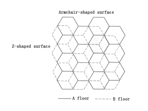
Figure 4 Schematic diagram of two end faces of carbon materials
In carbon materials, due to the incomplete heat treatment process and the unsaturated carbon atom valence, some impurity atoms, functional groups, etc. are easily adsorbed on the surface either physically or chemically. The most common impurity atoms are hydrogen and oxygen atoms. They may also exist as hydroxyl or carboxyl groups adsorbed on the surface. In addition, there are heteroatoms such as nitrogen and sulfur. The ratio of hydrogen atoms of mesophase carbon microbeads obtained at 500~600℃ can reach 30%~40%
(4) Structural defects
Due to the variety of hybrid forms when carbon atoms form bonds and the diversity of carbon material structure levels, carbon materials have various structural defects. Common structural defects include plane displacement, screw dislocation, and stacking defects.
Figure 5 Carbon material structural defects
In actual carbon materials, in addition to bonding through sp2 hybrid orbitals to form a hexagonal network structure, carbon atoms may also be bonded through sp and sp3 hybrid orbitals. Different forms of hybridization have different electron cloud distribution densities, leading to changes in the density of electrons in the carbon plane layer, deforming the carbon plane layer, and causing structural defects in the carbon plane layer. In addition, when there are other heteroatoms in the carbon plane structure, the size and charge of the heteroatoms are different from the carbon atoms, which will also cause structural defects in the carbon plane.
For carbon materials prepared by pyrolysis with organic compounds as precursors, the carbon atoms on the edges may still be connected with some functional groups, such as -OH, =O, -O-, -CH3, etc., during the carbon plane formation process. It will cause deformation of the planar structure of the carbon layer.
The carbon layer plane accumulation defect is the irregular arrangement of the carbon plane, which forms the layer accumulation defect in the surface material.
Pore defects are caused by pores left by the volatilization of gaseous substances during the process of preparing carbon.


