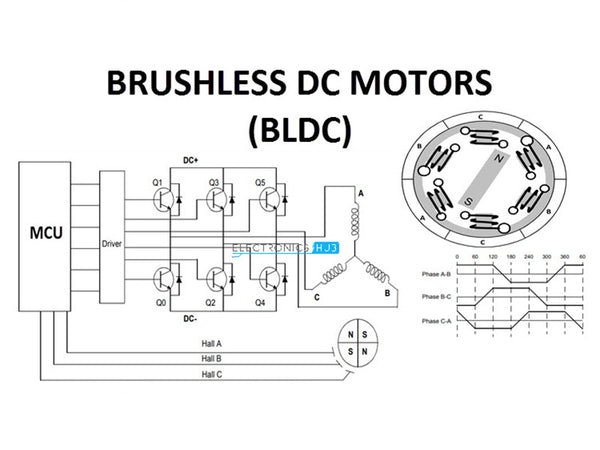
Permanent magnet brushless motor drive system has become the mainstream form of electric vehicle drive motor more and more because of its high efficiency, high power and high reliability. However, it also has problems such as high cost of permanent magnet materials and unadjustable magnetic flux. In recent years, research and development of electric vehicle motor drive systems have focused on permanent magnet brushless motors, which are expected to make full use of hydromagnetic materials and adjust air-gap magnetic fluxes, thus proposing various motor topologies. According to the stator working current and no-load back EMF waveform, permanent magnet brushless motors can be divided into permanent magnet brushless AC motors (BLAC, permanent magnet synchronous motors for short) and permanent magnet brushless DC motors (BLDC). Among them, BLDC has the advantages of simple control, low cost, and the elimination of speed sensors and position sensors, but it has inherent electromagnetic pulsation in principle, which is easy to generate noise at high speed, and it is difficult to obtain stable torque at low speed. Therefore, BLDC is only used in the accessory systems of hybrid electric vehicles (such as electric pumps, air conditioner compressors, etc.). In comparison, permanent magnet synchronous motors have the advantages of high power and torque density (light weight, small volume, large torque), high speed, wide speed regulation range, and high efficiency, and are widely used in the electric drive system of most hybrid vehicles.
The permanent magnet synchronous motor is developed from the electric excitation synchronous motor. The structure and operation principle of the two are basically the same. Compared with the electric excitation synchronous motor, the permanent magnet synchronous motor replaces the excitation coil excitation of the latter with the magnetic flux provided by the permanent magnet, saves the collector ring and brushes, simplifies the structure, and realizes brushless, thereby reducing the maintenance cost of the motor and improving the efficiency. Compared with induction motors, permanent magnet synchronous motors do not require excitation current, which can significantly improve the power factor, stator current and stator resistance loss are small, and there is no rotor resistance loss during stable operation, and the efficiency is high.
The torque of the permanent magnet brushless motor consists of two parts, namely the permanent magnet torque and the reluctance torque, namely

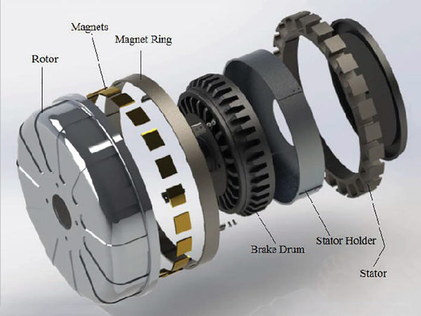
In the surface-mounted rotor structure, the permanent magnets are pasted on the rotor surface with epoxy glue. The manufacturing process is simple, the cost is low, and it is widely used. It is mainly suitable for trapezoidal wave permanent magnet synchronous motors. Since the magnetic permeability of the permanent magnet and the equivalent air gap length of the air close to the motor are equal to the sum of the actual air gap length and the radial length of the permanent magnet, the corresponding armature reaction and stator winding inductance are small. Since I and I in this motor are nearly equal, the reluctance torque in the motor is close to zero.
In a surface-inserted rotor structure, the permanent magnets are inserted or buried in the rotor surface, so the q-axis inductance is greater than the d-axis inductance, resulting in additional reluctance torque. The permanent magnets are inside the rotor and can run at high speed.
Compared with surface-mounted and surface-embedded permanent magnet synchronous motors, built-in permanent magnet synchronous motors are embedded in the rotor because the permanent magnets are embedded. It is equivalent to a magnetic isolation magnetic barrier in the direction of the magnetic circuit of the rotor shaft, which causes the anisotropy of the motor rotor, which makes the motor have a certain spatial saliency, and has more development advantages. The specific reasons are as follows.
①The water magnet of the built-in permanent magnet synchronous motor is located inside the rotor, which can effectively avoid the loss of magnetism of the permanent magnet. The rotor structure is firmer and the design is more flexible. It can be made into a high-speed motor, and the motor has good dynamic and static performance.
②The built-in hydromagnetic synchronous motor can effectively realize the field weakening control of the motor. When the motor terminal voltage reaches the voltage limit, the direct-axis demagnetizing current can be used to weaken the air-gap magnetic flux, which widens the speed regulation range of the motor and realizes the higher-speed operation of the motor.
③The eddy current loss on the rotor surface of the built-in permanent magnet synchronous motor is significantly lower than that of the surface-mounted permanent magnet motor, which effectively improves the efficiency of the motor.
④Due to the spatial saliency of the rotor structure of the built-in hydromagnetic synchronous motor, the q-axis inductance is greater than the d-axis inductance, which makes it easier to realize the position sensorless operation of the motor at low speed or even zero speed. Based on the above reasons, the built-in permanent magnet synchronous motor has broader development and application prospects, and is more suitable for electric vehicles.
Figure 1 shows the coordinate system relationship of the permanent magnet synchronous motor for vector control. The vector control of the permanent magnet synchronous motor can be attributed to the control of the d-axis and q-axis currents. For a given electromagnetic torque, there are many choices of d-axis and q-axis current combinations, which can produce different control methods. It mainly includes four control modes: id=0 mode, power factor cosφ=1 mode, constant flux linkage mode and stator current minimum control mode.

Figure 1-Permanent magnet synchronous motor coordinate system relationship
In the id=0 control mode, the stator current has only the q-axis component, and the control principle is the same as that of the DC motor. The characteristics of this mode are simple control, the stator current is proportional to the electromagnetic torque, the torque performance is good, there is no weak field current component, and it will not cause the demagnetization of the permanent magnet. And it can realize the minimum control of the stator current of the surface-mounted permanent magnet motor system, but when the salient pole ratio ρ≠l, there is no reluctance torque output, and the reluctance torque cannot be used effectively, and with the increase of the load, the stator current increases linearly, and the required inverter capacity is relatively large. The power factor of the motor is low, and the capacity of the motor and inverter is not fully utilized.
In the cosφ=1 control mode, the characteristic of the permanent magnet synchronous motor is that the power factor of the permanent magnet synchronous motor is controlled to be 1, that is, the direction of the stator current vector and the voltage vector coincides. The capacity of the inverter can be fully utilized, but the maximum torque that can be output by this method is small and cannot maintain a linear relationship with the armature current.
The constant flux linkage control mode controls the magnetic field component of the stator current of the permanent magnet synchronous motor, so that the air gap flux linkage of the motor is always kept constant during the operation, and is equal to the flux linkage generated by the rotor permanent magnet. In this mode, the power factor of the motor is high, the voltage is basically constant, and the torque is linearly controllable, but a large stator current magnetic field component is required to assist the magnetism.
The stator current minimum control refers to the optimal configuration of the d-axis and q-axis current components under the condition of a given torque to minimize the stator current, also known as the maximum torque-current ratio control. This control mode can reduce the copper consumption of the motor and improve the operation efficiency, so that the performance of the whole system can be optimized. In addition, since the required output current of the inverter is relatively small, the requirements for the inverter capacity can be relatively reduced.
Among the above control strategies, cosφ=1 control and constant flux linkage control are generally suitable for high-power motor systems because of their high power factor; while for small and medium-power motor systems, the torque response and overload capacity requirements are relatively high. Higher, suitable for id=0 control or minimum stator current control.
The permanent magnet synchronous motor adopts the field weakening speed expansion control, so that the motor can work in a very wide speed range, and can run at high speed and constant power to meet the needs of vehicle cruise. If the motor design satisfies (LdIr)/Ψm=1, it has the maximum weak field speed expansion capability, where Ψm is the water magnetic flux linkage, Ld is the d-axis winding inductance, and Ir is the rated current. Generally speaking, this ratio is less than 1, so the larger the value, the stronger the weak magnetic expansion capability.
The functional block diagram and topology of the permanent magnet synchronous motor for vector control is similar to that of the induction motor, as shown in Figure 2.
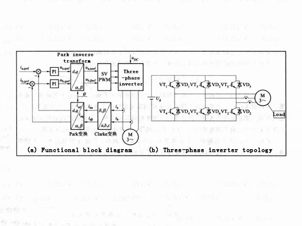
Figure 2 - Structure of induction motor vector control system
The vector control of the permanent magnet synchronous motor drive system is inseparable from the detection and initial positioning of the rotor position (or magnetic field). In the starting process of the motor, only by obtaining the accurate spatial positional relationship between the rotor and the stator, can the correct voltage phasor be obtained, thereby obtaining the appropriate rotational torque. According to the torque formula of the motor, if the angle of the rotor magnetic field is not determined relative to the angle of the stator winding when the power is turned on, the normal position and speed loop control cannot be realized. If the magnetic field angle 0 is arbitrarily selected as the initial value for control, the torque of the motor may be very small or zero, and the motor may also rotate in the opposite direction, which will lead to serious consequences in the hybrid vehicle drive system. An accurate and reliable rotor initial position detection device is a necessary condition for the normal startup of the permanent magnet synchronous motor drive system. When applying in large quantities, the initial position of the rotor must be determined first. The current automatic production technology instead of manual operation can greatly reduce the deviation of the initial position. The same batch of motors produced can basically be calculated and controlled with the same initial position angle.
Due to the interaction between the permanent magnet and the slotted armature core, the permanent magnet synchronous motor will inevitably generate cogging torque, resulting in torque fluctuation, vibration and noise, which affect the control accuracy and positioning accuracy of the system. Therefore, cogging torque must be weakened in the design and manufacture of high performance permanent magnet motors. At present, a lot of research results have been achieved on the weakening method of the cogging torque of the water magnet, which can be roughly divided into three categories: changing the magnetic pole parameters of the water magnet, changing the armature parameters, and a reasonable combination of the number of armature slots and poles.
During the working process of the permanent magnet synchronous motor, both the armature current and the air-gap magnetic flux change with a sinusoidal waveform, so a high-precision position signal sensor is required to complete the closed-loop control. This kind of position signal sensor mainly includes encoder and resolver, among which resolver can be used in occasions with high speed, high reliability and strong anti-interference ability, so it has been widely used in the electric drive system of electric vehicles. In addition, there are various ways to achieve position sensorless operation of the motor system. The earliest position sensorless control technology is collectively referred to as the fundamental wave excitation estimation method. These methods are generally suitable for position sensorless operation of the motor in medium and high speed situations. In the past ten years, research has mainly focused on estimating rotor position information using high-frequency signal composition methods to achieve position sensorless operation at low or zero speed of the motor and detection of the initial magnetic pole polarity of the rotor. However, there are still some difficulties in the large-scale application of position sensorless control in electric vehicles.