main content:
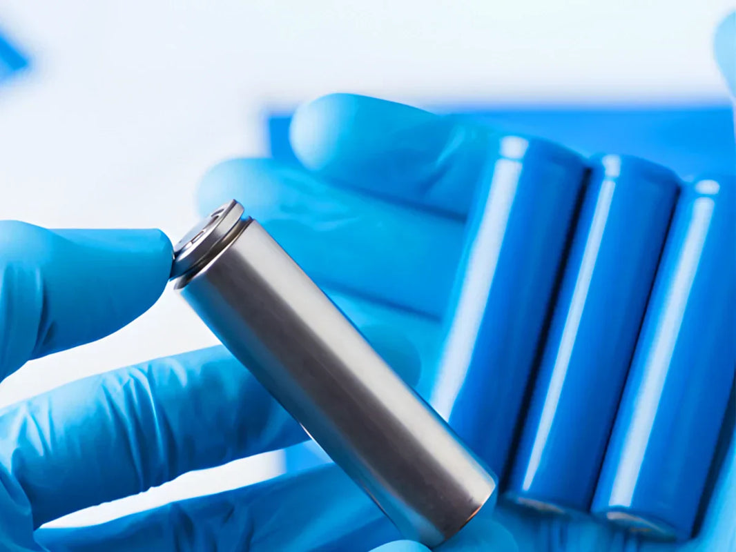
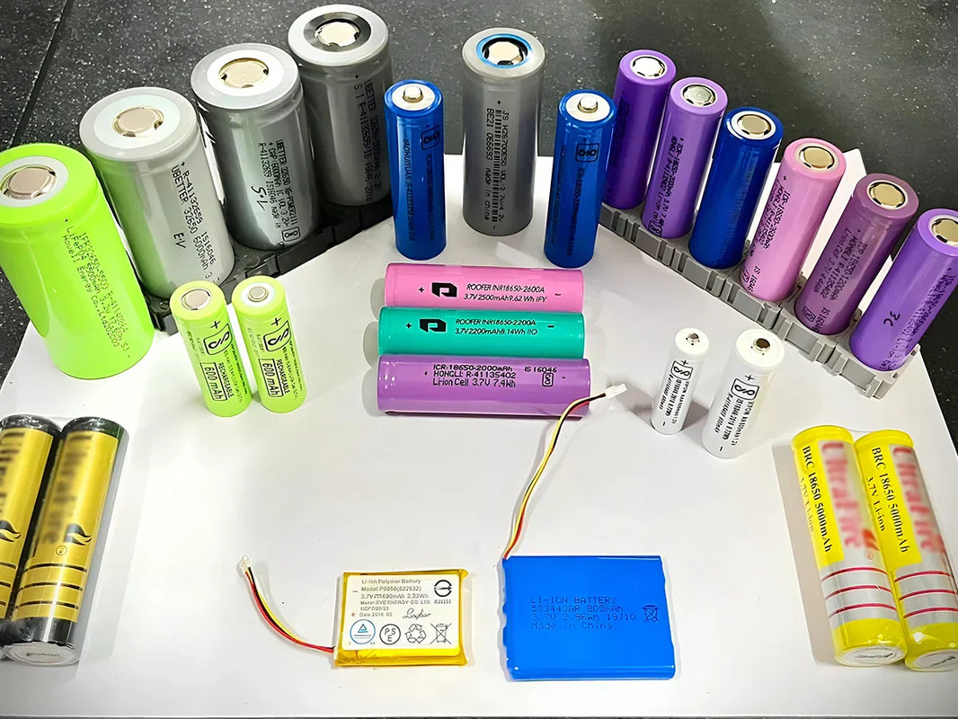
For cylindrical batteries, combined with the structure of the casing heat exchanger, a jacketed liquid cooling system can be designed. The battery is covered with a layer of annular cavity, and there is a liquid flow channel between the battery and the outer casing. The liquid working medium can be in direct contact with the battery, or not in direct contact with the battery, which can meet the high-efficiency heat dissipation of the battery under various conditions (even heating the battery in a low temperature environment).
The schematic diagram of the battery pack jacketed liquid cooling system is shown in Figure 1. The system consists of battery boxes/groups, casing heat exchangers, pumps, pipes, three-way valves, liquid distributors, etc. Each battery pack contains several battery modules.

Figure 1 - Schematic diagram of jacketed liquid cooling system
The cooling liquid from the outlet at the lower end of the casing heat exchanger is introduced into each battery module from the liquid separation head at the lower part of the battery module box under the action of the water pump installed in the upper pipe of the battery module box, each battery cell is fully cooled inside the battery module, and the cooled heating liquid is collected from the liquid separation head at the upper end of the box to the return pipe, and the heated liquid returns to the heat exchanger through the return pipe for cooling. Such a cycle provides continuous cooling of the battery pack. The thermal expansion valve installed at the inlet of the refrigerant pipe of the heat exchanger senses the temperature at the outlet end of the heat exchanger to adjust the valve opening, so that the cooling degree of the returning liquid can be controlled. When the battery works in different temperature settings, the temperature control three-way valve collects the temperature at the outlet of the battery module through the temperature sensor, compares the temperature value with the set temperature and responds, thereby controlling the switching between two different pipes. The heating device in the system is an auxiliary device specially designed to heat the battery when the electric vehicle runs in a relatively cold environment.
2. Single cell structure

In the jacket type liquid cooling system, the cylindrical battery cell is used as the base body, and the outer casing is installed to form a cooling flow channel in close cooperation, and they are connected and fixed by four ribs evenly distributed along the circumference. At the same time, it is reinforced with insulating glue to prevent the battery from falling off. The base body and the casing together form the battery cell structure (Figure 2). The gap between the base body and the casing ensures the smooth flow of the cooling liquid throughout the battery cell. The cooling liquid flows in from the lower flow channel of the battery cell, flows out from the upper flow channel of the single cell, and continues to flow through the battery wall to cool the battery.

Figure 2 - Schematic diagram of battery cell structure
3. The structure of the battery module

Each battery module includes several battery cells, and Figure 3 is a schematic structural diagram of the battery module. The battery cells are connected in sequence through the battery connecting pieces, and the fixing of the battery connecting pieces is pressed by the ribs on the top cover of the battery module. In order to prevent excessive compression of the battery by the ribs, a soft gasket can be added to the lower part of the battery connecting piece, which can also ensure the vertical direction of the battery cell while fixing the connecting piece. After the battery cells are installed in place, the gap between the outer wall of the battery case and the inner wall of the pores of the bottom plate can be sealed with a material with good sealing performance (such as silicone glass glue) to prevent the cooling fluid from infiltrating and causing cooling loss.

To ensure that the temperature between the cells remains uniform, the cooling fluid must flow uniformly and steadily through each cell flow channel. The fluid inlet and outlet of the battery module respectively adopt a diversion bottom cover and a diversion top cover that can divide the flow evenly, and the diversion top cover and the diversion bottom cover are fixed and installed on the module frame by suitable screws. A temperature sensor is installed at the outlet end of the battery module to collect the battery temperature in real time. In order to connect the batteries between the battery modules in series, it is necessary to lead out the module power supply through the electrode terminals screwed on the guide top cover. In order to ensure a good sealing of the liquid inside the module, a raw material tape can be wrapped around the electrode terminal.
In the actual operation of electric vehicles, the positioning and installation of each module in the battery pack not only involves the maintenance and replacement of a single battery module, but also directly affects the safe operation of the entire battery pack. Considering the manufacturing, installation, positioning, connection and other factors, the modules in the battery pack are generally installed in a neat arrangement.


