


main content:
Solving the problem of electromagnetic interference can generally start from three aspects, namely suppressing the electromagnetic emission of the electromagnetic interference source, cutting off or weakening the propagation and coupling path of the electromagnetic interference, and improving the anti-interference ability of the circuit or equipment. Among them, suppressing the electromagnetic emission of electromagnetic interference sources is the most important solution.
Therefore, in the study of electromagnetic interference solutions for electric vehicle power systems, we should generally start with electromagnetic interference sources. That is to analyze the mechanism of electromagnetic interference, and take measures to suppress the source of electromagnetic interference. When the specified electromagnetic compatibility index is still not achieved after taking measures, measures should be taken from two aspects: cutting off or weakening the coupling path of electromagnetic interference and improving the anti-interference ability of the equipment. Common measures to suppress the electromagnetic emission of electromagnetic interference sources are shielding, filtering and grounding.
1. Shield

Shielding is the metal isolation between two space areas to suppress the propagation and coupling of electromagnetic energy from one space to another. Shielding is a solution to suppress electromagnetic interference by cutting off the coupling path of electromagnetic interference. According to the different objects shielded by the shielding shell, electromagnetic shielding can be divided into two types: active shielding and passive shielding. For the electric vehicle system, active shielding refers to the measures taken to shield the electromagnetic interference source in the system in order to prevent the electromagnetic interference source inside the system from radiating electromagnetic noise and affecting the normal operation of the surrounding equipment or system. Specifically, the shielding body is used to surround the components, equipment and even the electromagnetic interference source of the system in the electromagnetic environment of the power system, so as to prevent the electromagnetic interference from spreading to the outside world. Passive shielding refers to the measures taken to shield the sensitive receiving equipment in order to prevent the sensitive receiving equipment or components in the system from being subjected to electromagnetic interference from the external electromagnetic interference source of the system. That is, the shielding body is used to surround the receiving circuit, sensitive equipment and even the entire system in the power system to prevent them from external electromagnetic interference.
The material of the electromagnetic shielding shell is usually made of materials with good electrical conductivity or both electrical and magnetic conductivity properties, and the object to be shielded or shielded is placed inside the shell. The shield can absorb or reflect electromagnetic waves, thereby preventing electromagnetic waves inside the casing from radiating outward or preventing electromagnetic waves from radiating outside the casing. In practical applications, the effectiveness of electromagnetic shielding depends to a large extent on the structure of the shielding casing, that is, the continuity of the casing's electrical conductivity. Holes or openings in the housing can cause leakage of electromagnetic waves. In the power system of pure electric vehicles, the cable harness passing through the shielding shell is the main factor causing the decrease of shielding effectiveness.
In general, shielding can be divided into two types: electromagnetic shielding and electrostatic shielding. Electromagnetic shielding mainly refers to shielding measures taken to prevent electromagnetic interference caused by alternating magnetic fields, electric fields or electromagnetic fields; and electrostatic shielding mainly refers to shielding measures taken to prevent electromagnetic interference caused by constant magnetic fields and electrostatic fields. Electromagnetic shielding is widely used in the power system of pure electric vehicles. In practical applications, electromagnetic shielding technology has high requirements on the conductive continuity of the shielding structure used, and requires good grounding performance of the shielding structure. Electromagnetic shielding materials often used in practical applications include metal materials such as copper, steel and aluminum.
2. Filtering 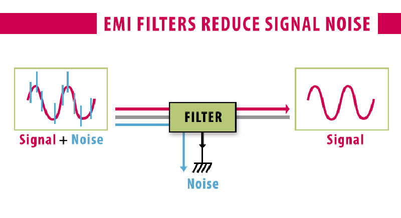
A common type of electromagnetic interference in electric vehicle power systems is conducted electromagnetic interference, and the most widely used method for suppressing conducted electromagnetic interference is to add a filter between the electromagnetic interference source and the disturbed equipment, and the filter can reduce or suppress the unwanted electromagnetic energy of the power system. Whether it is used to suppress the electromagnetic interference generated by the electromagnetic interference source in the electromagnetic environment of the power system, or to enhance the anti-interference ability of the receiving circuit in the system, filter technology can be used. There are usually many types of filters such as low-pass, high-pass, band-pass, and band-stop. But the essence of all kinds of filters is to filter out unwanted high-frequency electromagnetic noise through series inductors, parallel capacitors or necessary resistors in series and parallel. The principle of the filter to suppress electromagnetic interference is to use the high-frequency characteristics of capacitors and inductors to consume the energy of high-frequency interference signals, so that the interference signals enter the disturbed equipment or system as little as possible.
The wiring harness in the electric vehicle power system has strong antenna characteristics, which can not only receive the electromagnetic waves radiated into the system from the outside, but also radiate the electromagnetic energy generated by the system to the surrounding space. The specific performance is that the wire harness may not only act as an electromagnetic interference source to cause electromagnetic interference to surrounding equipment or systems, but also may conduct electromagnetic energy outside the system or equipment to the disturbed equipment as a receiver of the disturbed device. In addition, when the wire harness transmits high-frequency signals, it is easy to cause crosstalk between the wire harnesses. Although filters are mainly used to suppress conducted electromagnetic interference, they can also be used to suppress radiated electromagnetic interference through reasonable design of filters. When the radiated electromagnetic interference is serious, the corresponding electromagnetic interference filter can usually be installed at the output end of the electromagnetic interference source and the input end of the disturbed device to filter out the interference signal and achieve the purpose of electromagnetic compatibility. Therefore, filters can be used in electric vehicle systems to suppress the adverse effects of electromagnetic interference.
According to different functions, filters can generally be divided into electromagnetic interference type filters and signal selection type filters. The design of the filter in the electric vehicle power system should ensure that it can avoid electromagnetic interference when the circuit is working, and at the same time does not affect the circuit's reception of useful signals. The main function of the signal-selective filter is to filter out signals that are useless to the circuit while ensuring that the amplitude and phase characteristics of the useful signal are minimally affected. For example, there are many signal selection filters in the high frequency amplifier stage or intermediate frequency amplifier stage in general receivers and measuring receivers, and the main function of the electromagnetic interference filter is to suppress the electromagnetic interference signal in the circuit. This question mainly introduces electromagnetic interference type filters. According to different use occasions, electromagnetic interference filters can be divided into power line filters, telephone line filters, signal line filters, control line filters and data line filters. These filters are all low-pass filters, and the number corresponding to the filter name is the useful frequency component that needs to pass through this type of filter, and the component not at this frequency belongs to the stop band of the filter.
The main indicators of electromagnetic interference filter include frequency characteristics, impedance, rated voltage, rated current and leakage current.
(1) Frequency characteristics. The rate characteristic reflects the insertion loss of the filter as a function of frequency. For the passband, its insertion loss should be small; for the stopband, it should have a large insertion loss. The insertion loss L is defined as:

In the formula:
L—insertion loss, dB;
E1——The voltage established by the signal source on the load resistance when the filter is not connected, V;
E2——The voltage established by the signal source across the load resistance through the filter, V.
With different applications, the maximum particle rate of the EMI filter passband is also different. For example, the power line filter mainly passes the power frequency signal (50Hz, 60Hz or 400Hz); the signal line, control line and data line filter need to be determined according to the signal frequency band transmitted. When the upper limit of the frequency that needs to be transmitted is relatively high, it is often higher than the lowest frequency of the electromagnetic interference desired to be filtered out, and the required passband and stopband crossover occurs. In this case, the use of filters is difficult to solve the problem, and other measures must be taken (such as optoelectronic isolators, etc.).
(2) Impedance. The filter is located between the signal source and the load. In theory, its input impedance should match the signal source, and the output impedance should match the load. But because the filter's working frequency band (including stopband and passband) is very wide (for example, the stopband frequency band of the power filter used in the electromagnetic shielding room is required to be from 10kHz to more than ten GHz, and the passband is mainly 50Hz), in such a wide frequency range, it is difficult to achieve good impedance matching at the input and output terminals, and because the impedance of the signal source itself (for example, the source of the power filter is the public power grid) changes greatly, it is even more impossible to achieve matching. Therefore, it is necessary to specify a fixed source impedance and load impedance when measuring the frequency characteristic curve, and the impedance of the filter in actual use cannot be consistent with the impedance of the test characteristic. This situation may cause the frequency characteristic curve of the filter to be different from the results measured in the laboratory.
For this reason, a type of electromagnetic disturbance filter has appeared, which is deliberately designed to have a serious impedance mismatch in the stopband frequency band, so as to achieve high insertion loss in the stopband through reflection. This type of filter is also called a reflection filter.
(3) Rated voltage. The filter must have a voltage rating high enough to guarantee reliable operation under all expected conditions. This is because when the applied voltage exceeds the rated voltage, the capacitor or resistor in the filter may be broken down or burned. Therefore, the rated voltage is particularly important for power line filters or when the input signal contains pulses.
(4) Rated current. The rated current refers to the maximum allowable current that does not destroy the resistance and inductance performance of the filter in continuous use. The rated current is related to the current-carrying capacity and working leakage of the switches, fuses, and inductance coil wires inside the filter. In addition, it is important to note that if magnetic material is used in the inductor in the filter, its ampere-turns at rated current should not push the magnetic material's operating point into saturation. Because once it enters the saturation region, the inductance will become smaller, affecting the overall filtering characteristics, and even distorting the waveform output of the filter in severe cases.
(5) Leakage current. For the power line filter, when the load is open, the current between the input phase line and the ground line is called the leakage current of the filter. The leakage current is caused by the capacitor connected between the phase line of the filter and the ground to filter out the common mode disturbance. Sometimes due to the large capacity of the capacitor, the leakage current of the filter for 220V/50Hz power supply can be as high as several amperes. However, the tiny leakage current filter working under the same voltage and frequency can control the leakage current to about 2mA. The main problems caused by leakage current are: in the power supply circuit, if a leakage current protector is connected in front of the filter, the leakage current of the filter is enough to make the protector act; in addition, since leakage current is capacitive, if a large number of high leakage current filters are installed on the same grid at the same time, the power factor will decrease. For the same filter, the magnitude of the leakage current is proportional to the operating voltage at its input.
3. Ground

Grounding refers to establishing a conductive path between the electronic and electrical components (or equipment) of the system and the grounding reference point, which is one of the effective measures to suppress electromagnetic interference. Grounding is an important performance of the pure electric vehicle power system, and whether the entire system can work stably has a great relationship with its grounding performance. If the grounding performance of the pure electric vehicle power system is poor, it will not only fail to play its due role, but may weaken the shielding effectiveness of the equipment that has been properly shielded in the power system., or make the filter unable to play a full role, making it difficult to suppress the electromagnetic interference in the system. A good basic ground plane or reference point is the basis for reliable and undisturbed operation of a pure electric vehicle powertrain.
An ideal ground plane refers to a reference object with zero impedance and zero potential. However, since a voltage drop occurs when the current passes through a finite impedance, and the impedance of the ground wire is not zero, this leads to a potential difference on the ground wire. Therefore, the potential difference between different ground points in a system is always non-zero. Especially when the frequency of the current signal flowing through the ground wire is high, the inductance characteristics of the ground wire will be more obvious, and the impedance of the wire at this time is much greater than the resistance of the DC wire, so the potential difference of each point on the grounding line is much larger than the potential difference at DC or low frequency. It can be seen that an ideal ground plane does not actually exist. The potential difference between the points on the ground line may cause the malfunction of the circuit. Whether the potential difference between different grounding points in the pure electric vehicle power system can be reduced to close to zero and the magnitude of the grounding current drop depends on the grounding efficiency of the grounding point. The grounding efficiency is related to the grounding method. In order to ensure the grounding efficiency of the power system, the grounding method of the grounding point should be carefully selected.
Common grounding methods include single-point grounding, multi-point grounding, mixed grounding, and floating grounding. In order to ensure the grounding efficiency, different grounding methods can be adopted according to the working frequency of the electromagnetic signal.
(1) Usually, when the frequency range of the signal operation is within 1MHz, the single-point grounding method can be used.
(2) When the frequency range of the signal operation is above 10MHz, the impedance of the ground wire will increase due to the inductive characteristics of the ground wire, and the resulting parasitic capacitance may cause unexpected paths, so it is no longer suitable for single-point grounding, and multi-point grounding can be adopted at this time.
(3) When the frequency range of signal operation is between 1 and 10 MHz, the grounding method to be adopted needs to be determined according to the length of the grounding wire. If the length of the grounding wire is not greater than 1/20 of the minimum signal wavelength, a single-point grounding method can be adopted; when the length of the grounding wire is greater than this value, a multi-point grounding method is required.
In addition, the selection of the grounding wire will also affect the grounding performance. Generally, a flat conductor can be used as the grounding wire, or multiple conductor wells with a large distance can be used as the grounding wire. At the same time, the ground wire at the input end of the system should be as short as possible to minimize the possibility of the system being disturbed.


