

 main content:
- 1. LiCoO2 material
- 2. LiNiO2 material
- 3. LiMn2O4 material
- 4. Phosphoric acid system compounds
1. LiCoO2 material
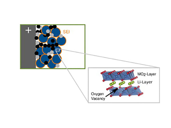
The composition formula of the cathode material L.iMO2 (M=Ni, Co) is a layered rock salt structure (α-NaFeO2 structure), belonging to the R3m group, as shown in Figure 1. They all have a basic skeleton in which oxygen ions are arranged in a cubic close-packed arrangement of ABC stacks. LiNiO2 and LiCoO2 have the same number of anions and cations, and the oxygen octahedral gaps are occupied by cations. They have a two-dimensional structure, Li+ and Co3+ (or Ni3+) They are arranged alternately on the (111) plane of the cubic structure and cause the lattice distortion to become hexagonal symmetry. Li+ and Co3+ (or Ni3+) are located at the (3a) and (3b) positions, respectively, and O2- is at the (6c) position. Taking LiCoO2 as an example, there are differences due to the interaction of Li, Co and O atoms. Therefore, in the…Li-O-Co-O-Li-O… layer, there is the strongest chemical bond between Co3+ and O2- , O-Co-O layers are bound together by Li+ electrostatic interaction, so that the entire unit cell structure is stable. In contrast, the O layer is closer to the Co layer (interlayer spacing μ=0.260 nm), where the (003) surface is its most probable cleavage surface.
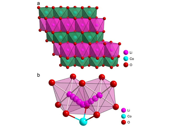
Figure 1 Schematic diagram of the structure of the cathode material LiCoO2
It can be seen from Figure 1 that in the structure of this compositional material, lithium and central transition metal atoms form separate layers parallel to the oxygen atomic layer, and they are stacked on each other to form a hexagonal superlattice. Their lattice constants are given in Table 1.
| Compound | a0/nm | c0/nm | Volume/nm3 | rLi+/rM3+ | Crystal symmetry |
| LiCoO2 | 0.2805 | 1.406 | 0.0319 | 1.314 | Hexagonal crystal system (R3m) |
| LiNiO2 | 0.2885 | 1.420 | 0.0341 | 1.286 | Hexagonal crystal system (R3m) |
Table 1 LiMO2 (M=Ni, Co) lattice constant data
LiCoO2 has three phases, namely the layered structure of HT-LiCoO2, the spinel structure of LT-LiCoO2 and the rock salt phase of LiCoO2. The oxygen atoms in the layered structure of LiCoO2 adopt a distorted cubic close packing, and the cobalt and lithium layers are alternately distributed On both sides of the oxygen layer, it occupies octahedral pores; the spinel structure of LiCoO2 oxygen atoms are arranged in an ideal cubic close-packed arrangement, the lithium layer contains 25% cobalt atoms, and the cobalt layer contains 25% lithium atoms. Li+ and Co3+ are randomly arranged in the rock salt phase crystal lattice, and the lithium layer and the cobalt layer cannot be clearly distinguished.
The layered CoO2 framework structure provides a two-dimensional tunnel for the migration of lithium atoms. When the battery is charged and discharged, the migration process of Li+ in the active material can be expressed by the following formula:
Charging: LiCoO2→xLi++Li1﹣xCoO2+xe
Discharge: Li1﹣xCoO2+yLi++xe→Li1﹣x+yCoO2 (0<x≤1, 0<y≤x)
The structural changes and electrochemical properties of HT-LiCoO2 and LT-LiCoO2 during charge and discharge are not consistent. When charging, as x increases from 0 to 0.5, the unit cell parameter c/a of HT-LiCoO2 increases from 5.00 to 5.14. At x≈0.5, HT-LiCoO2 transforms from a hexagonal unit cell to a monoclinic unit cell; while LT- The LiCoO2 unit cell parameter c/a is almost unchanged (see Table 2).
| sample | a/nm | c/nm | c/a |
| HT-LiCoO2 | 0.2816(2) | 1.408(1) | 5.00 |
| HT-Li0.74 CoO2 | 0.2812(2) | 1.422(1) | 5.06 |
| HT-Li0.49CoO2 | 0.2807(2) | 1.442(1) | 5.14 |
| LT-LiCoO2 | 0.28297(6) | 1. 3868(4) | 4.90 |
| LT-Li0.71CoO2 | 0.28304(4) | 1. 3866(2) | 4.90 |
| LT-Li0.49CoO2 | 0.28273(2) | 1.3851(1) | 4.90 |
Table 2 Unit cell parameter data of HT-LiCoO2 and LT-LiCoO2 and their delithiation state
Compared with HT-LiCoO2/Li assembled batteries, LT-LiCoO2/Li batteries have a low operating voltage and are stable in some non-aqueous electrolytes. However, the cobalt atoms in the lithium layer of LT-LiCoO2 will hinder the reversible deintercalation of lithium atoms, resulting in a slower mass transfer rate of Li+ in LT-LiCoO2; LT-Li1-xCoO2 has high reaction activity during delithiation and is easy to form on the electrode surface Passivation film, so it is difficult to realize the practical use of LT-LiCoO2 material.
2. LiNiO2 material
The ideal LiINiO2 belongs to the hexagonal crystal system. The oxygen atoms are arranged in a slightly distorted cubic compact structure, and lithium atoms and nickel atoms are alternately distributed on both sides of the oxygen atomic layer, occupying the octahedral gaps, as shown in Figure 2. The layered NiO2 provides a two-dimensional tunnel for lithium atoms to migrate. Therefore, the stability of the layered structure determines the cycle performance of LiNiO2. For LiNiO2 layered compounds, the structural stability is related to the lattice energy. Therefore, the O-M-O bond energy plays a vital role in the electrochemical performance of LiNiO2. The 3d electron arrangement of the outermost layer of Ni3+ is t62ge1g.. According to the molecular orbital theory (MOT), the bonding orbital with lower energy is already occupied, and the other electron can only occupy the σ2p in the oxygen atom, and the orbital formation has a higher energy. This leads to the weakening of the Ni-O bond bond energy. In addition, in the hexagonal layered structure of LiNiO2, NiO6 octahedrons are easily deformed by the Jahn-Teller effect. Therefore, relatively speaking, the hexagonal layered structure of LiNiO2 is not as stable as LiCoO2. When studying the structure of LixNiO2 and its delithiation process, it was found that when x=0.7, the crystal lattice changes from hexagonal crystal form R3 to monoclinic, and when x=0.3, it changes from monoclinic crystal form to hexagonal crystal form R3' Transition, while its unit cell volume shrinks. This is because during the charging and discharging process, Ni3+ is oxidized to Ni4+( t62ge0g ), and the interlayer attraction of the NiO2 layer becomes larger. Under the action of the Jahn-Teller effect, the NiO2 layer shrinks to cause a phase change of LiNiO2. Therefore, LiNiO2 is not resistant to overcharge. At the same time, because Ni4+ is highly oxidizing, it is easy to react with the electrolyte in the battery, making its thermal stability poor.
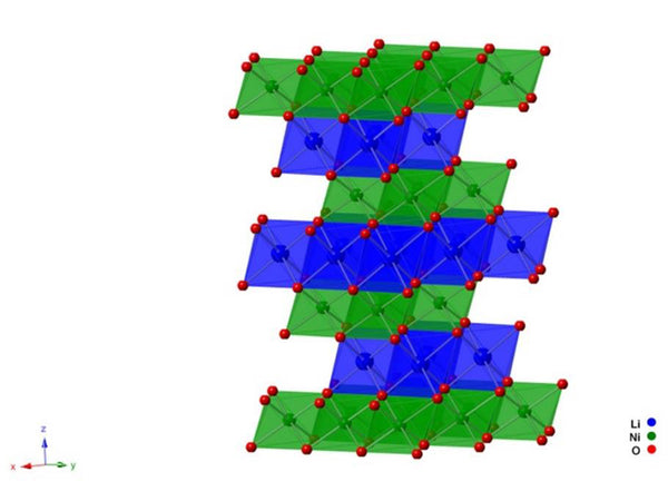
Figure 2 Schematic diagram of the crystal structure of LiNiO2
Now take lithium nickelate as an example to discuss the correlation between its energy band change and its electrochemistry. With lithium-intercalated graphite as the negative electrode of the battery, the reaction formula of the LiC6/NiO2 battery during the discharge process is
LiC6(s)+ NiO2(s)→6C+ LiNiO2(s)
∆Er=E(LiNiO3)+6E(C)—E(NiO2)—E(LiC6)
Deiss et al. calculated the average open circuit voltage (3.05V) of LiC6/LiNiO2 using the full potential linearized amplification plane wave method, which was about 15% lower than the experimental value (3.57V).
Someone used the Hartree-Fock method in the CRYSTAL98 program package to calculate the average voltage of the LiC6/LiNiO2 lithium-ion secondary battery as 4.10V. Compared with the experimental value of 3.57V, the relative error is +15%. The calculations show that the net charges of Ni and O atoms in NiO2 are 2.068 and -1.034, respectively; the net charges of Li, Ni and O atoms in LiNiO2 are 0.982, 1.872 and -1.427, respectively. Compare the net charges on the corresponding atoms of NiO2 and LiNO2 It shows that in the discharge process, Li is almost completely ionized after being embedded in NiO2 (net charge +0.982), and the negative charge is mainly transferred from Li atoms to O atoms, and only a small amount (-0.196) is transferred to Ni atoms, so the charge of Ni changes It is very small, which explains the experimental result that the Jahn-Teller effect of LiNiO2 is very weak. In addition, the lithium ion in Li0.5 NiO2, the intermediate product of lithium insertion, has two possible diffusion paths in the crystal: straight line and broken line. The calculation results show that the potential barrier for diffusion through the broken line is small, which is likely to be the way for lithium ion diffusion.
The electronic density of states of NiO2 and LiNiO2 are shown in Figure 3. It can be seen from Figure 3 that for NiO2 [see Figure 3(a)], the Fermi level is -3.8a.u. The inner orbitals of Ni and O, which have the lowest energy below the Fermi level, are located in the range of -0.8 to -0.36au, which are composed of bonded orbitals eg, a1g and t1u (mainly contributed by the 2p orbitals of O) and non-bonded orbitals t2g (Ni’s dxy, dxz and dyz orbitals) constitute the energy bands, these energy bands are fully filled. The energy band composed of the antibonding orbital eg* (Ni's dx²-y², dz² orbital) is above the Fermi energy (-0.2~0.4a.u. region) and is not occupied by electrons. It can be seen that there is a large energy gap (0.33a.u., about 9eV) between the full-filled band with the highest energy and the full-empty band with the lowest energy, so NiO2 can be considered as an insulator.

Figure 3 Electronic density of states of NiO2 and LiNiO2
It can be seen from the electron density of states diagram (b) of LiNiO2 that as a lithium atom is inserted into NiO2, the eg energy band moves downwards, and the low energy of the p energy band of O moves upwards, indicating that the O-Ni bond is weakened. That is, the Ni-O bond length is stretched from 189.9pm to 197.9pm to illustrate this point. The weakening of the σ bonding between O and Ni leads to the downward shift of the anti-bonding energy band eg*, and the Fermi energy is located in the middle of the partially occupied eg* energy band. It shows that LiNiO2 is a conductor. The possible mechanism of lithium ion secondary battery charging and discharging is explained from the electronic structure.
3. LiMn2O4 material
There are many compounds formed in the Li-Mn-O system. The main materials that can be used as positive electrode materials are LiMn2O4, LiMnO2, Li4Mn5O9, and Li4Mn5O12. These compounds are prone to structural transformation during the synthesis and charge and discharge process, which affects the electrochemical performance of the material. negative effect. Here we introduce the [Mn2O4] skeletal structure of spinel LiMn2O4. The framework is a three-dimensional network of coplanar tetrahedrons and octahedrons. This network is conducive to the diffusion of Li atoms in it, as shown in Figure 4.

Figure 4 The crystal structure of spinel LiMn2O4
As shown in Figure 4, the spinel-type LiMn2O4 belongs to the Fd3m space group, lithium occupies the tetrahedral (8a) position, manganese occupies the octahedral (16d) position, and oxygen (O) occupies the face-centered cubic (32e) position. Therefore, Its structure can be expressed as Li8a[Mn2]16dO4. Since the side length of the unit cell of the spinel structure is twice that of the ordinary face-centered cubic structure, a spinel structure can actually be considered as a complex cubic structure, including 8 ordinary face-centered cubic unit cells. Therefore, a spinel unit cell has 32 oxygen atoms, 16 manganese atoms occupy half of the 32 octahedral interstitial sites (16d), the other half of the octahedron (16c) is empty, and lithium occupies 64 tetrahedral interstitial sites. 1/8 of (8a), it can be seen that lithium atoms are deintercalated in the three-dimensional network of Mn2O4 through the gaps of adjacent tetrahedrons and octahedrons along the channels 8a-16c-8a.
In this configuration, the oxygen atoms are closely packed cubically, 75% of the Mn atoms are alternately located between the cubic tightly packed oxygen layers, and the remaining 25% of the Mn atoms are located in adjacent layers. Therefore, in the delithiation state, there are enough Mn ions in each layer to maintain the ideal cubic tightly packed state of oxygen atoms, and lithium ions can be directly inserted into the tetrahedral interstitial sites composed of oxygen atoms.
In LixMn2O4, the deintercalation range of lithium atoms is 0<x≤2, and when the range of lithium intercalation or deintercalation is 0<x≤1.0, a reaction occurs:
LiMn2O4=Li1-xMn2O4+xe+Li+
At this time, the average valence state of Mn is 3.5~4.0, the Jahn-Teller effect is not very obvious, so the crystal still maintains its spinel structure, the corresponding Li/LixMn2O4 output voltage is 4.0V, and when 1.0<x≤2.0 , The following reactions occurred:
LiMn2O4+ye+yLi=Li1+yMn2O4
When the charge-discharge cycle potential is about 3V, that is, when 1<x<2, the average valence of manganese is less than +3.5 (that is, manganese ions mainly exist in +3 valence), which will cause a serious Jahn-Teller effect and make spinel The crystal structure changes from a cubic phase to a tetragonal phase, and the c/a value will also increase. This structural deformation destroys the spinel framework. When the range of this change exceeds a certain limit, it will destroy the three-dimensional ion migration channel, and lithium will be removed. The embedding is difficult, which leads to the deterioration of the electrochemical cycle performance of the material on the macroscopic level.
In LixMn2O4 with a spinel structure, in the region of 0<x<1.0, a single spinel structure cannot be completely maintained during the process of lithium ion insertion, but is accompanied by multiple phase transitions. Lithium ion insertion is divided into three processes: when 0.27<x<0.6, the insertion exists in the reaction between the two cubic phases; when 0.6<x<1.0, it is an insertion process in the cubic phase; when 1.0<x<2.0 ,A phase change between the cubic phase and the tetragonal phase occurs. When 1>1, the voltage drops sharply by about 1V, which is mainly caused by Jahn-Teller distortion, that is, [MnO6] changes from symmetric Oh type to asymmetric D4h type. There is a three-phase model for crystal transformation: when 0<x<0.2, it is cubic single-phase region A;when 0.2<x<0.4 is two-phase coexistence region A+B; when 0.45<x<0.55 is cubic single-phase region B; 0.55 When <x<1, it is a cubic single-phase area. There is a two-phase coexistence zone between phase B and phase C (0.55<x<0.95); and for the Jahn-Teller distortion occurring at x=1.0, the damage to the lattice configuration is small, which will affect the cycle performance of LiMn2O4 The impact is small.
The intercalation process of lithium ions does not occupy 8a positions one by one in order, but has a more complicated pattern. This is because when lithium ions are intercalated into the lattice of [Mn2O4], part of Mn4+ is reduced to Mn3+, but the spinel skeleton remains unchanged. Because the position of tetrahedron 8a is coplanar with tetrahedral vacancy 48f and octahedral vacancy 16c, The tetrahedral vacancy 8a and the octahedron 16d occupied by Mn4+ share four faces, the tetrahedral vacancy 48f and 16d share two faces, and the octahedral vacancy 16c is co-sided with the six adjacent 16d. Under the action of electrostatic force, the inserted lithium ions first enter the position of the tetrahedron 8a. However, entering other vacancies will require greater activation energy. Since each octahedral position is coplanar with 8a on two opposite faces, when x<0.5, lithium ions occupy half of the 8a positions, which is similar to [Mn2O4] crystal The superstructure of the lattice is related, that is, there is a sub-lattice. At this time, the entire crystal appears to be in a long-range order and no longer in a short-range order. It happens that one sub-lattice is full and the other is completely empty. The insertion of lithium ions into half of the 8a position will effectively reduce the repulsive force between adjacent lithium ions, so that the spinel structure after insertion of lithium ions can maintain the lowest energy state. The macroscopic expression is that when x=1/2, the crystal There is a sudden jump in cell parameters. At this time, the embedding process of two-phase cubic close packing is shown, and the reaction formula is as follows:
[□][Mn2]16dO4+1/2Li+→[□1/2Li1/2Mn2]16dO4
When 0.5<x<1, lithium ions are inserted into the 8a position of the other half:
[□1/2Li1/2Mn2]16dO4+1/2Li+→[Li8a][Mn2]16dO4
When the amount of insertion is further increased, the 8a position has been filled, and the inserted lithium must enter the 16c position of the octahedron; at this time, the lattice structure of [Mn2O4] changes from cubic crystal to tetragonal crystal, and the space group changes from Fd3m For F41/adm, Jahn-Tellel distortion occurs, changing from a cubic phase to a tetragonal phase.
[Li8a][□16c][Mn2]16dO4+Li+→[Li8a][Li16c][Mn2]16dO4
4. Phosphoric acid system compounds
Phosphoric acid system compound cathode materials are represented by LiFePO4 with olivine structure and Li3V2 (PO4) 3 with NASICON structure.
LiFePO4 has a regular olivine structure, which belongs to the orthorhombic system (D162hPmnb), and its structure is shown in Figure 5.
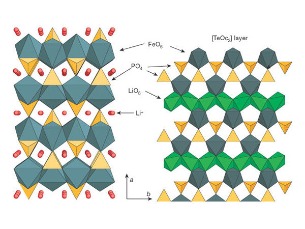
Figure 5 Schematic diagram of the three-dimensional structure of lithium iron phosphate
Li3V2 (PO4) 3 is a triclinic crystal system. In its three-dimensional structure, PO43- replaces the relatively small O2-, which helps increase the stability of the structure and accelerate the migration of lithium ions, and ion substitution can pass through two aspects To change the potential. One is the induction effect, which changes the ion pair and changes the energy level of metal ions; the other is to provide more electrons and change the concentration of lithium ions, which facilitates the occurrence of redox reactions. In the three-dimensional structure, the metal octahedron and the phosphate tetrahedron share oxygen atoms. Each metal vanadium atom is surrounded by 6 tetrahedral phosphorus atoms, while the tetrahedral phosphorus is surrounded by 4 vanadium octahedrons. This structure forms a three-dimensional structure. In the network structure, lithium atoms are in the pores of this framework structure, and 3 four-fold crystal positions are lithium atoms, resulting in 12 positions of lithium atoms in a structural unit. Its structure is shown in Figure 6.
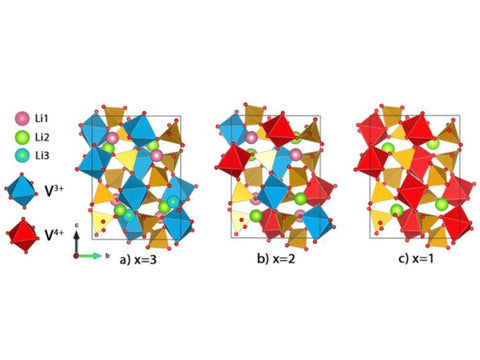
Figure 6 Schematic diagram of two different crystal forms of Li3V2 (PO4) 3


