
Main content:
In a small wind power system that operates independently, the alternator driven by the wind turbine needs to be equipped with an appropriate rectifier to charge the battery.
Rectifier can generally be divided into two categories: mechanical rectifier and electronic rectifier. The characteristics of the former are that the former completes the process of converting from alternating current to direct current through mechanical action; the latter completes the rectification from alternating current to direct current through the unidirectional movement of electrons in the rectifier element process. The mechanical rectifier is generally a rotating mechanical device, so it is also called a rotating rectifier; the components of the electronic rectifier are all static components, so it is called a static rectifier. Static electronic rectifier is mainly used in wind power generation systems.
Electronic rectifier can be divided into two categories: uncontrolled rectifier and controllable rectifier.
1. Uncontrolled rectifier

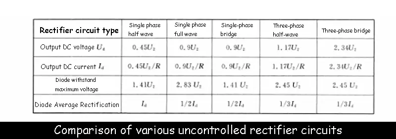
Uncontrollable rectifier is composed of diodes. Common rectifier circuits include single-phase half-wave rectifier circuits, single-phase full-wave (double half-wave) rectifier circuits, single-phase bridge rectifier circuits, and three-phase half-wave rectifier circuits (zero-type rectifier circuits). circuit) and three-phase bridge rectifier circuit. The circuit diagrams of various rectifier circuits, the output voltage (rectified voltage) waveform, the output DC voltage, the output DC current, the maximum reverse voltage withstand by the diode and the average current flowing through each diode are shown in the table.
The output DC voltage Ud given in the figure below refers to the average value of the pulsating DC voltage obtained on the load, and the output DC current Id refers to the average value of the DC current flowing through the load; U2 refers to the effective value of the AC power supply voltage. The AC lake refers to the effective value of the phase voltage. According to the figure below, the diodes under different rectifier circuits can be reasonably selected. In fact, for the sake of safety, the diodes with higher reverse voltage values should be selected.
2. Controlled Rectifier
The rectifier is composed of a thyristor (or a silicon controlled rectifier). As we all know, a silicon controlled rectifier is an electronic device composed of four layers of semiconductors and three junctions. The silicon controlled rectifier is connected to the outside with three electrodes, namely the anode. A, cathode C and control electrode G, as shown in the figure below.
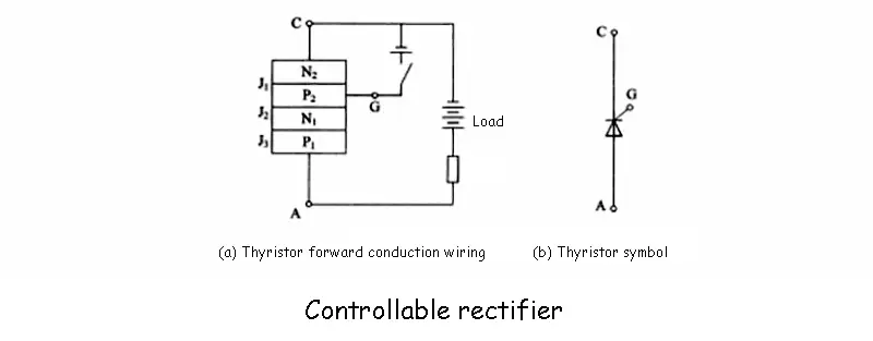
When the anode of the thyristor rectifier is connected to the positive pole of the power supply, the cathode is connected to the negative pole of the power supply, and the control pole is connected to the control voltage that is positive to the cathode, the thyristor is turned on, and the external circuit load connected to the thyristor will have a current passing through it. As shown in Figure (a) above, once the thyristor is turned on, even if the control voltage is canceled, the thyristor will remain on, so the control voltage is often in the form of a trigger pulse, that is, after the thyristor is turned on, the control voltage will be lost. effect. To turn off the thyristor, the forward anode voltage must be reduced to a certain value, or the thyristor is disconnected, or a reverse voltage is applied between the anode and the cathode of the thyristor.
According to the characteristics of the thyristor's trigger conduction, changing the angle a of the trigger voltage signal from the starting point (called the control angle or the ignition angle), the angle θ at which the thyristor can be controlled to conduct is called the conduction angle. In the single-phase circuit, the starting point of the sinusoidal curve is used as the starting point for calculating the angle of the mouth, and in the multi-phase circuit, the intersection point of each phase waveform is used as the starting point for calculating the α angle. Due to the change of the conduction angle of the thyristor, the size of the rectified voltage (DC voltage) on the external circuit load connected to the thyristor also changes, which is the controlled rectification.
Common controllable rectifier circuit forms include single-phase full-wave controllable rectifier circuit, single-phase bridge controllable rectifier circuit, three-phase half-wave cavity rectifier circuit, three-phase bridge half-controlled rectifier circuit and three-phase bridge rectifier circuit.
Read more: Other equipment in the wind farms


