

With the vigorous promotion of new energy policies and the implementation of relevant measures in various countries, renewable energy around the world has been developing quickly. And distributed generation (DG), represented by photovoltaic power generation, has gradually occupied an important strategic position in economic development because of its clean and efficient characteristics.
Taking China as an example, according to the Energy Research Institute's forecast, by 2025, the total installed photovoltaic capacity (such as home solar power system) will reach 730 million kilowatts, accounting for 24% of the country's total installed capacity; in 2035, photovoltaic power generation will become the first among all power types; in 2050, photovoltaics will become China's largest power source, and the total installed capacity of photovoltaic power generation will reach 5 billion kilowatts, accounting for 59% of the country's total installed capacity.
In the future, solar photovoltaic power generation will occupy an important position in energy consumption in China and even the world.
With the rapid development of the photovoltaic energy industry and the increasing penetration rate of new energy in the distribution network, leakage protection issues in power distribution systems containing photovoltaic power sources have become the key to electricity safety. Current sensor is an important segment in the development of the energy industry. Its core technology carries the important mission of precise control and efficient energy saving, and is crucial to promoting the implementation of green transformation and upgrading.
Main content:
1. Leakage protection issues in distribution systems
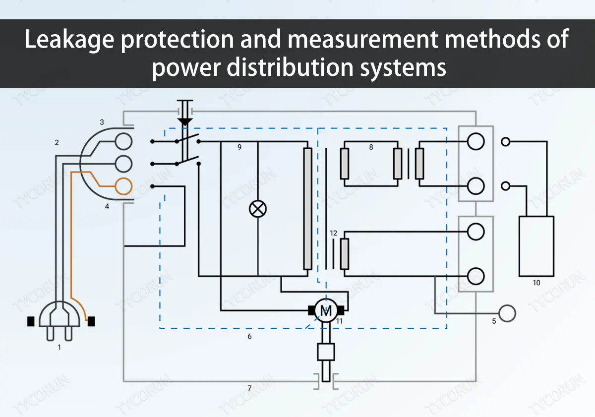
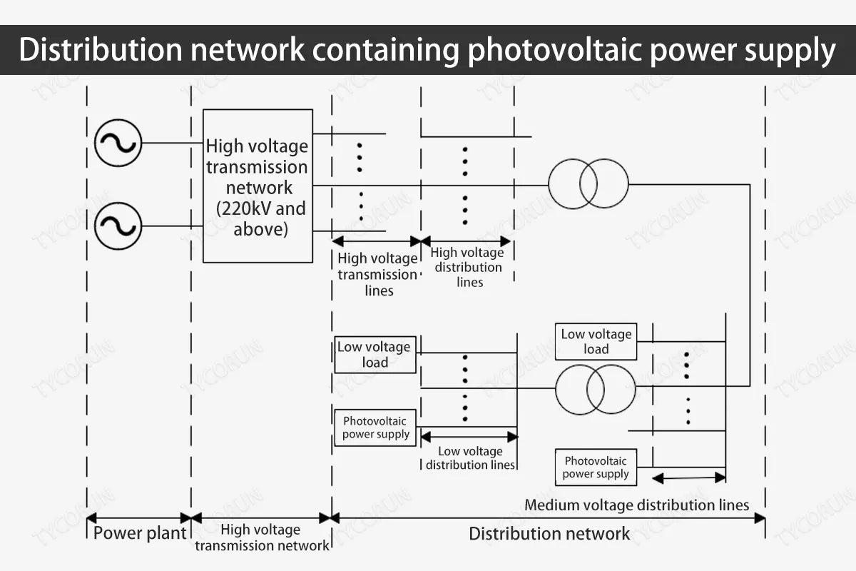
After the photovoltaic power supply is connected, it, together with the energy storage device, energy conversion device, AC and DC loads and protection devices, form a small power generation and distribution system, as shown in the figure below.
Since the power distribution system containing photovoltaic power supply contains DC link equipment, the current transmission is different from the traditional AC transmission, and the leakage current form that may be generated during the transmission process is also more complex. The popularization of power distribution systems containing photovoltaic power sources, while improving the structure of the energy industry, also faces more severe electricity safety challenges.
As the rainy season approaches, current leakage occurs frequently. Due to the large capacity of the power distribution system containing photovoltaic power sources, the tiled area of the components is large. The system itself has strong capacitive characteristics and is easily affected by environmental humidity, resulting in system capacitive leakage. Especially in the morning and evening or in rainy weather, it is more serious, and it is likely to be accompanied by leakage protection equipment tripping (if the system has installed one).
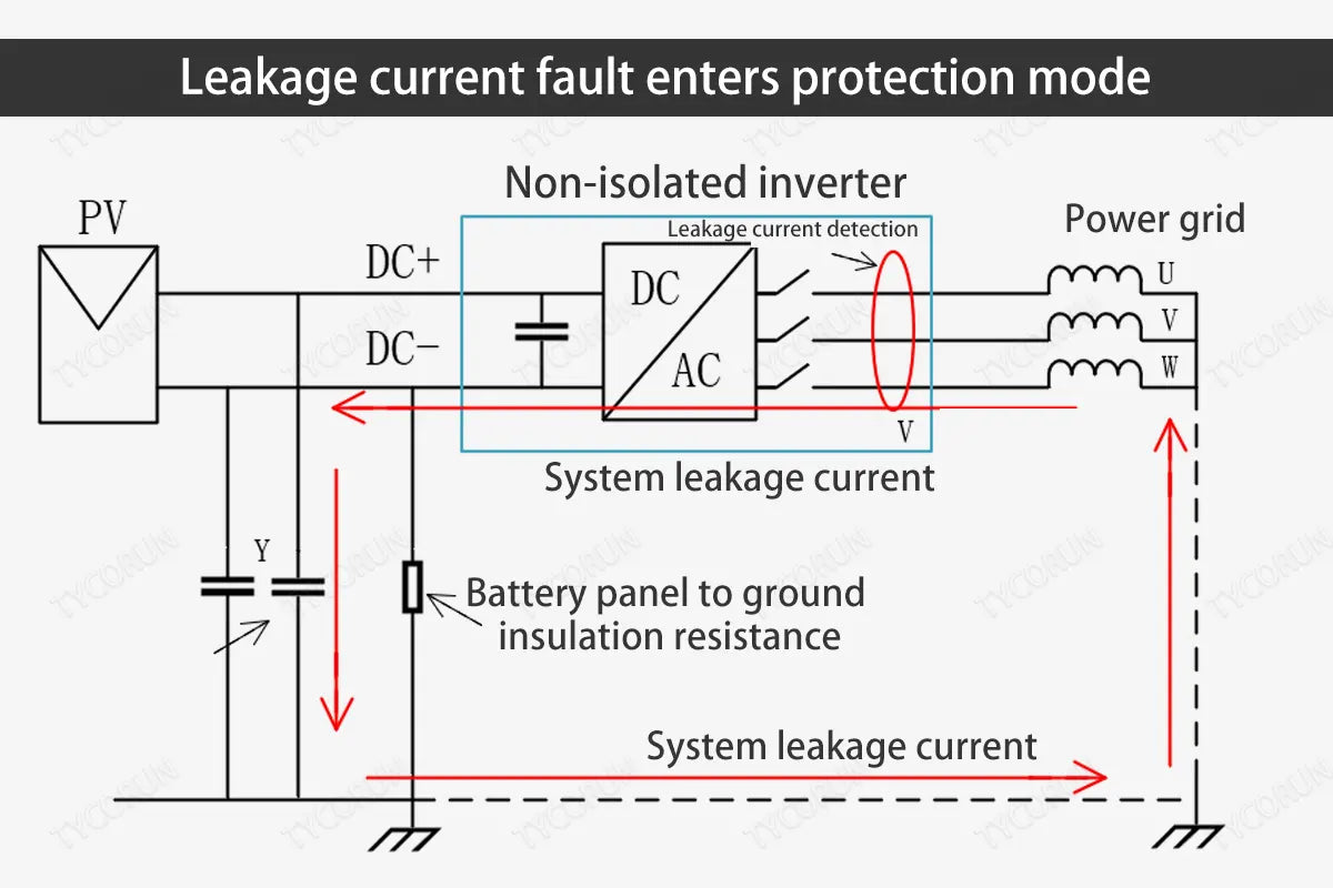
The main manifestations are: the inverter (such as 2000w inverter or 3000w inverter) is disconnected from the power grid and enters protection mode. The screen displays the error message "Leakage Current Fault 01/02/03/04", which may also cause leakage protection equipment to act (if it is installed).
This fault indicates that the inverter and leakage protection have detected leakage current from the photovoltaic system to the ground. According to the requirements of national standard (NBT 32004-2018) 6.7.2, if this fault occurs, the inverter must stop working immediately and enter the inverter protection mode to protect personal and equipment safety, as shown in the figure below.
2. Measurement methods of distribution system leakage current
At present, for power distribution systems containing photovoltaic power sources, the development direction of leakage protection technology mainly focuses on three aspects: measurement methods, protection methods and the research and development of leakage protection products. The current sensor is the core of the current measurement part of the leakage protector. How to effectively extract the weak current signal has become a key and difficult point in the measurement research of leakage current.
Considering that the power distribution system containing photovoltaic power supplies contains DC equipment, in order to solve the problem of residual current detection containing DC signals, this article mainly introduces and compares the measurement problems of DC leakage current, mainly including DC current transformer, Hall current sensor and fluxgate current sensor.
① DC current transformer
The DC current transformer mainly reflects the size of the measured current by indirectly changing the excitation current through the change of the measured current to the inductive reactance of the iron-core coil. The principle diagram is as shown in the figure below.
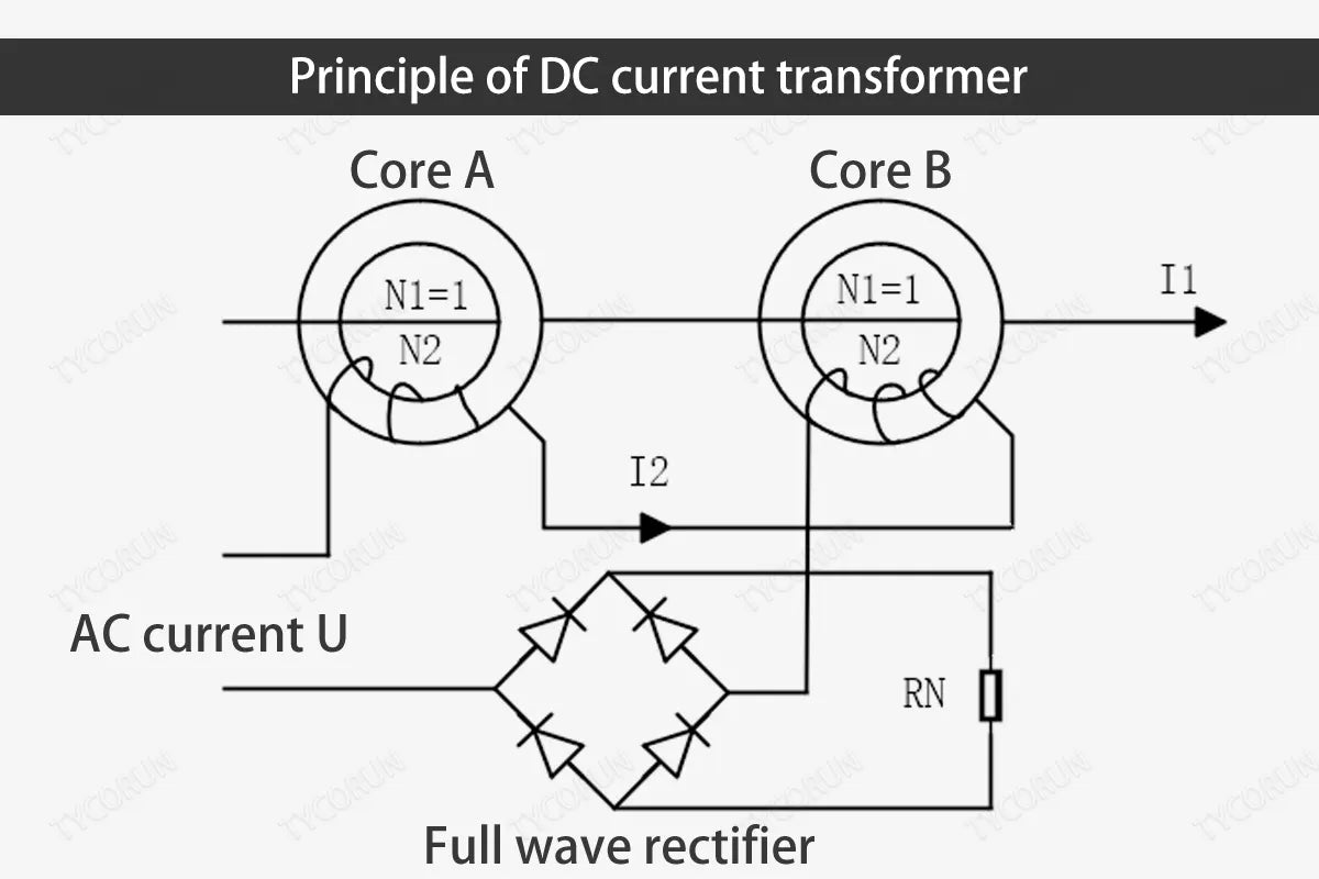
At present, in power systems, in addition to measuring DC current, DC current transformers are also widely used in rectification systems, acting as current feedback components, or used to control and protect other components.
② Hall current sensor
The main component of the Hall current sensor is the Hall element. The Hall element can sense the magnetic field around the energized wire and convert the magnetic field into a voltage output in a certain proportion.
The advantage of the Hall current sensor is that it can measure current in any waveform, but the disadvantage is that the temperature drift problem is serious. Since the Hall device is made of semiconductor material, changes in the external ambient temperature will affect the carrier concentration of the device, thereby affecting the accuracy of the measurement value. Therefore, in some applications that require high reliability, Hall current sensors have certain disadvantages.
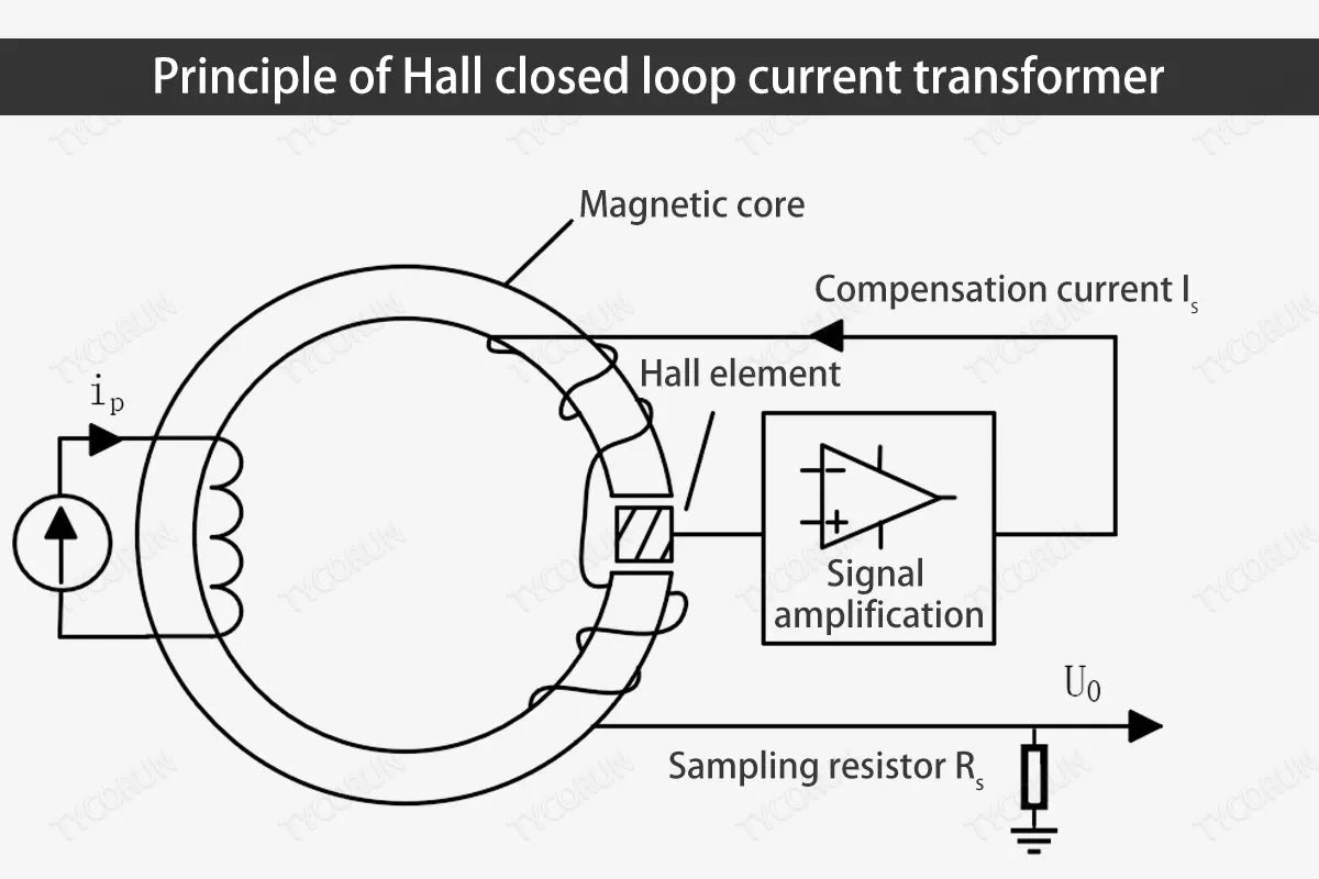
The principle of Hall closed-loop current transformer is shown in the figure below. The circuit is mainly composed of magnetoelectric conversion part, amplification part and drive compensation circuit part. The entire measurement loop forms a closed-loop system.
③ Fluxgate sensor
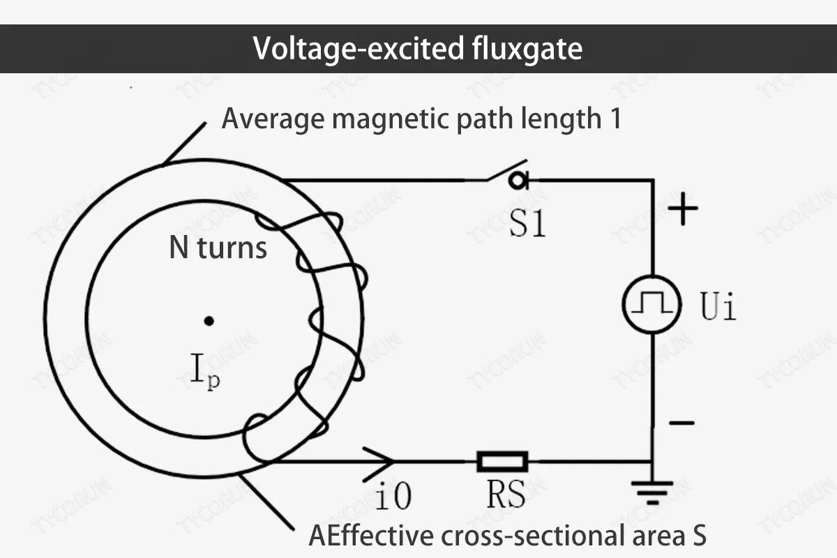
The basic principle of fluxgate technology is to utilize the characteristics of soft magnetic materials that are prone to magnetic saturation. Through periodic AC excitation signals, the magnetic core reaches or approximately reaches a periodic magnetic saturation state, and the magnetic saturation frequency is twice the frequency of the excitation signal.
When there is no external magnetic field, the two adjacent magnetic saturation waveforms are exactly the same. When the external magnetic field or the magnetic field generated by the external current passes through the magnetic core, it is equivalent to adding an external bias to the magnetic field in the magnetic core, changing its adjacent two. The depth of the submagnetic saturation state (or changes in its arrival time), from which the applied magnetic field or current can be measured. The voltage excited flux gate is shown in the figure below.
When compare the above three leakage current measurement methods, and the analysis results are as follows.
Comparison of current measurement methods:
|
Measurement method |
DC current transformer |
Hall current sensor |
Fluxgate current sensor |
|
Current type |
Pulsating DC |
AC-DC |
AC-DC |
|
Measuring range |
10~20kHz(or higher) |
0~200kHz(or higher) |
0~10kHz(or higher) |
|
Measurement accuracy |
High, the response speed is fast |
High, the response speed is slow |
High, the response speed is fast |
|
Anti-interference |
When the load current is large, the asymmetric placement of the current-carrying conductor in the transformer core can easily produce false residual current. |
Easily affected by external magnetic fields; greatly affected by DC component. |
Not affected by external magnetic fields; strong anti-interference ability |
|
Temperature characteristics |
Good |
Poor, zero point drift is likely to occur when the temperature changes (<200ppm/C, 0~70℃) |
Good (typical value 30ppm/℃, -25~70℃) |
|
Quality-price ratio |
High |
Relatively high |
Relatively high |
So we can see that the fluxgate current sensor has the advantages of simple structure, miniaturization, low power consumption, high stability, high shock resistance, high accuracy, low drift, good linearity and strong anti-magnetic ability. The advantages of fluxgate current sensor compared with Hall current sensor include:
- The fluxgate current sensor amplifies the differential signal of the positive and negative excitation currents to eliminate the zero offset error and the error caused by magnetic field interference, thereby improving the sensitivity and stability of the fluxgate sensor; while the drift problem of zero point of the Hall sensor mainly comes from the drift of the operational amplifier in the signal amplification circuit. The temperature drift is due to its semiconductor properties. The semiconductor scattering coefficient, carrier density and are all affected by temperature. Therefore, the Hall sensor is more sensitive to temperature, which in turn affects the detection accuracy.
- The fluxgate core does not require opening cutting, its structure is more complete, higher strength, better durability, can better resist physical damage and external interference, the output stability of the core is better, and the reliability is higher. The Hall element of the Hall sensor needs to be connected to the opening when working, so the sensitivity is reduced and the production cost is relatively high.
- The strong magnetic field generated by the fluxgate sensor during its working process makes the sensor less affected by external noise and interference, and is less likely to be interfered; while the Hall sensor usually requires the use of amplifiers and other circuits due to its small detection effect of the magnetic field. With enhancements, these circuits themselves can also introduce noise and interference. In addition, Hall sensors are also susceptible to factors such as ambient temperature and magnetic field direction. Therefore, the fluxgate sensor has better anti-interference performance than the Hall sensor.
References
① Wu Pingan, Zhang Shaohai, Yi Zhiming. Comparison of DC system leakage detection methods [J]. North China Electric Power Technology, 2003(02):52-54.
② Wang Xuenan, Wang Yafei. DC residual current measurement device based on magnetic modulation principle[C]. China Technical Electrical Engineers Association Low Piezoelectric Professional Committee. 2010, No.15: 478-484.
③ Min Yingzong. An AC/DC sensing method based on adaptive magnetic modulation technology with double feedback properties[C], 2001 IEEE International Workshop on Applied Measurements for Power System, 2011.9:48-52.
④ Li Qian. Research on leakage protection of power distribution system containing photovoltaic power supply[D]. Hebei University of Technology, 2019.
⑤ Lu Zhijun. Research on residual current detection technology based on fluxgate B-type current transformer [D]. Shanghai Institute of Electric Power, 2022.
⑥ ZEINELDIN H, EL-SAADANY E, SALAMA M, Distributed generation micro-grid operation: control and protection[C] // Proceedings of the Power Systems Conference: Advanced metering, Protection, Control, Communication, and Distributed Resources,2006 PS’06:F, 2006, IEEE.
Related posts: top 10 solar inverters in Australia, global top 10 best solar inverter brands, top 10 best power inverter companies in Europe


