

As renewable energy solutions and the industry of home solar power system continue to improve, so do the methods and design options for implementing energy solutions. How to measure the current of a photovoltaic system can have a huge impact, where the high-side current measurement of Hall current sensor can play an important role in improving the optimization, reliability and efficiency of micro-inverters.
By comparing the high-side and low-side sensing schemes, this article will demonstrate the advantages of high-side Hall current sensor, including accurate detection of short circuits, minimization of system power consumption, reduction of heat dissipation, and improvement of system reliability.
Main content:
What is the current test method of micro inverter
Micro-inverters, such as 500w inverter and 1000w inverter, are becoming key technologies to make renewable energy more accessible and scalable. Using photovoltaic (PV) panels in combination with micro-inverters, the generated electricity can be converted directly into alternating current and incorporated into the grid. Efficient conversion requires accurate current measurement for better power conversion, precise system control and protection.
There are usually two main ways to measure the current of photovoltaic panels: low side and high side sensing, of which high side sensing has more advantages, especially when considering the use of Hall current sensors. The measurement of the current can be carried out on the high side or the low side.
When sensing at the low side, the sensing device needs to be connected in series between the load and the ground, and measure the current returned from the load; On the high side, the sensing device is connected in series to the PV input and can directly measure the current flowing into the system load (as figure below).
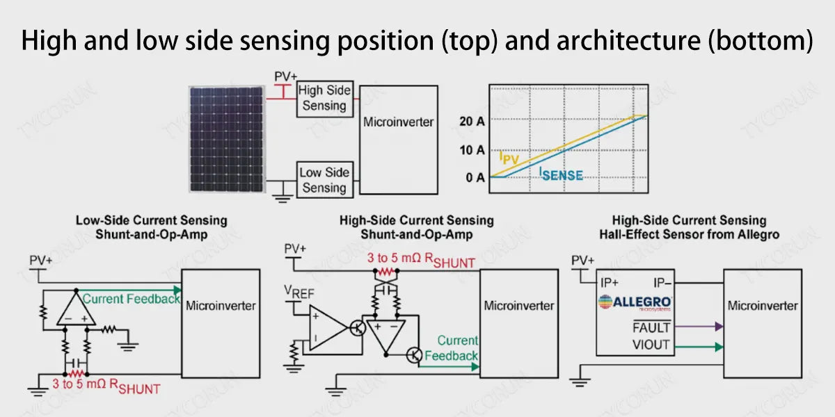
In photovoltaic system, the traditional method of low side current measurement is to use current shunt amplifier, which is favored because of its relatively low cost and simple implementation. However, the implementation of current shunt on the high side requires more complex circuitry and higher performance components.
Compared to shunt and amplifier solutions, Hall current sensor offers simple, flexible low or high side implementations while being isolated from the current circuit to be measured. All of the various methods for high or low side current measurement in micro-inverters present a degree of trade-off, and as described below, some have a huge impact on a particular system. The following will tell you about the advantages of Hall current sensor for micro-inverters.
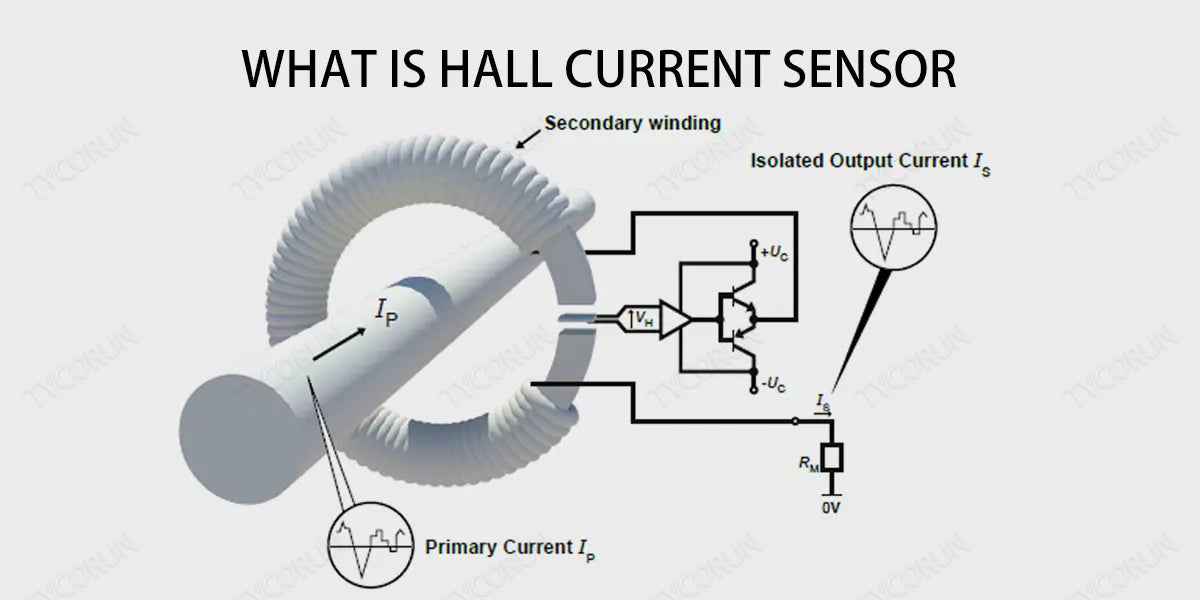
What is Hall current sensor
Hall current sensor is mainly suitable for the isolation and conversion of AC, DC, pulse and other complex signals. Through the principle of Hall effect, the transformed signal of Hall current sensor can be directly collected by various acquisition devices such as AD, DSP, PLC, and secondary instruments.
Hall current sensor is widely used in current monitoring and battery applications, inverter power supply and solar power management system, DC screen and DC motor drive, electroplating, welding applications, frequency converter, UPS servo control system current signal acquisition and feedback control.
Advantages of Hall current sensor
Enhanced reliability
In DC conversion circuits, short circuit detection can affect user safety and the life of photovoltaic equipment. Micro-inverters need to operate under extreme temperature and weather environmental conditions, making them prone to early component failures that can lead to short circuits. Detecting and reacting to possible short circuits in micro-inverters is important for maintaining stable and safe operation of equipment and power grids.
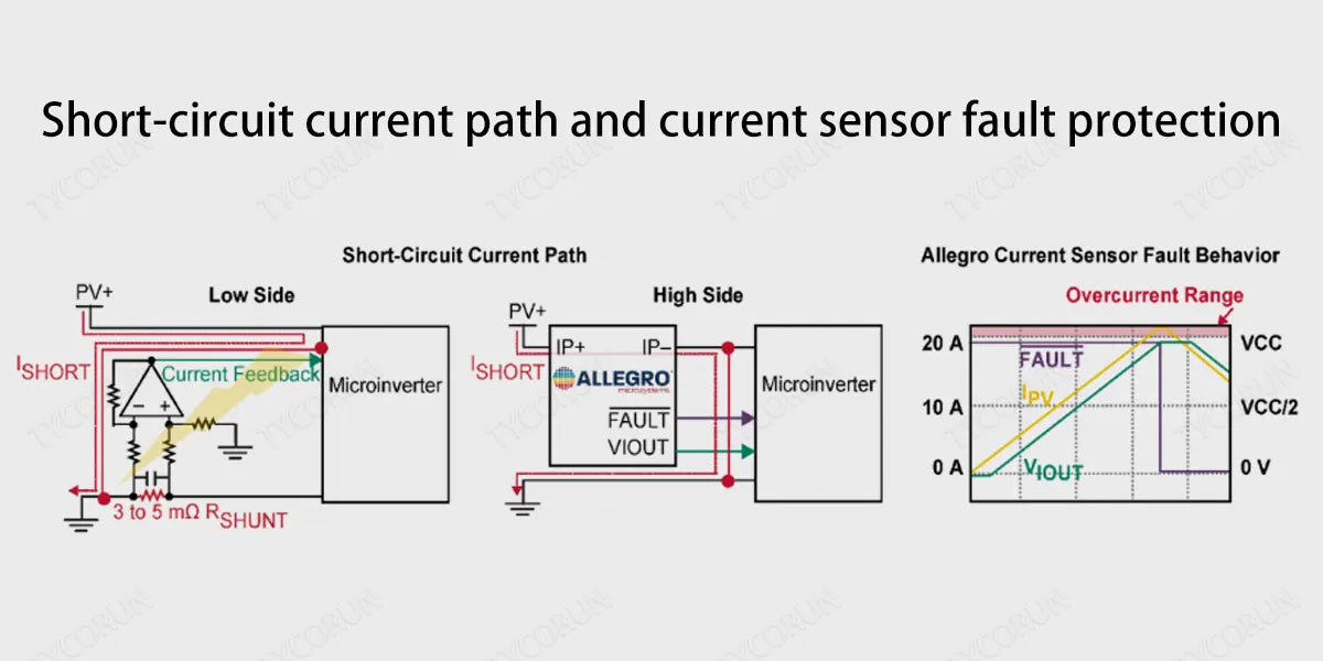
In this regard, low-side current sensors have a disadvantage because they only measure the PV return current and do not provide insight into the current behavior of the upstream circuit, and short circuits in micro-inverters can bypass low-side measurements and thus affect system function (see figure left).
Although the severity of the impact varies, in the most extreme cases, a short circuit can cause the entire system to fail. Improving the ability to detect these events enhances the system's insight and responsiveness in these scenarios, enabling fault protection solutions to avoid or prolong system replacement.
Hall current sensor can be easily integrated at the PV input to sense the current flowing into a micro-inverter. The provided fast response device detects current spikes caused by short circuits and transmits them to the system controller to apply protective measures.
Hall current sensor also incorporates built-in features such as overcurrent fault protection to protect the system if the input current exceeds the micro inverter rating, or if the installation and panel are improperly configured (see figure right). This high reliability of the input sensing circuit can help avoid early equipment failures and extend the overall life of the device.
Power consumption and thermal impact
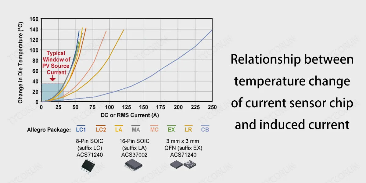
When examining the power consumption and thermal impact of any shunt solution, it is important to consider the systems that the solution needs to monitor. The current of photovoltaic panels ranges from 0 to 25A, depending on wattage and lighting conditions. Any shunt plus op amp solution requires a trade-off between gain and offset voltage to optimize power loss.
Shunt size has an impact on system heat dissipation, so this is part of the consideration. Larger sizes increase power consumption (and thus cost), but allow for lower gain configurations and mitigate the effect of op amp offset errors on small shunt voltages.
In micro-inverters, a 3mΩ shunt can add 2W of heat to the entire system, which can affect sensing accuracy and may require thermocouple calibration. The use of auxiliary means such as copper panels and thermal vias can dissipate the heat in the area, but this increases the cost and development time.
When thermal parameters are considered in the design of best solar inverter, the Hall current sensor consumes very little power and introduces very little heat, and if we make a simple comparison, the combined resistance of the integrated conductor and the static operating current of the device will not exceed 1W (typically 0.4W and 0.8W).
In addition, Hall current sensor is able to measure the full PV input current range with minimal contribution to system heat. This is important, especially considering that heating devices can reduce their service life in close proximity to the system's high-capacity capacitors.
If exposed to excessive heat, it can cause electrolyte leakage of electrolytic capacitors, which reduces the total capacitance, increases ESR, and leads to premature failure. Capacitor failure can cause instability or short circuit of the micro-inverter, which can damage the entire system.
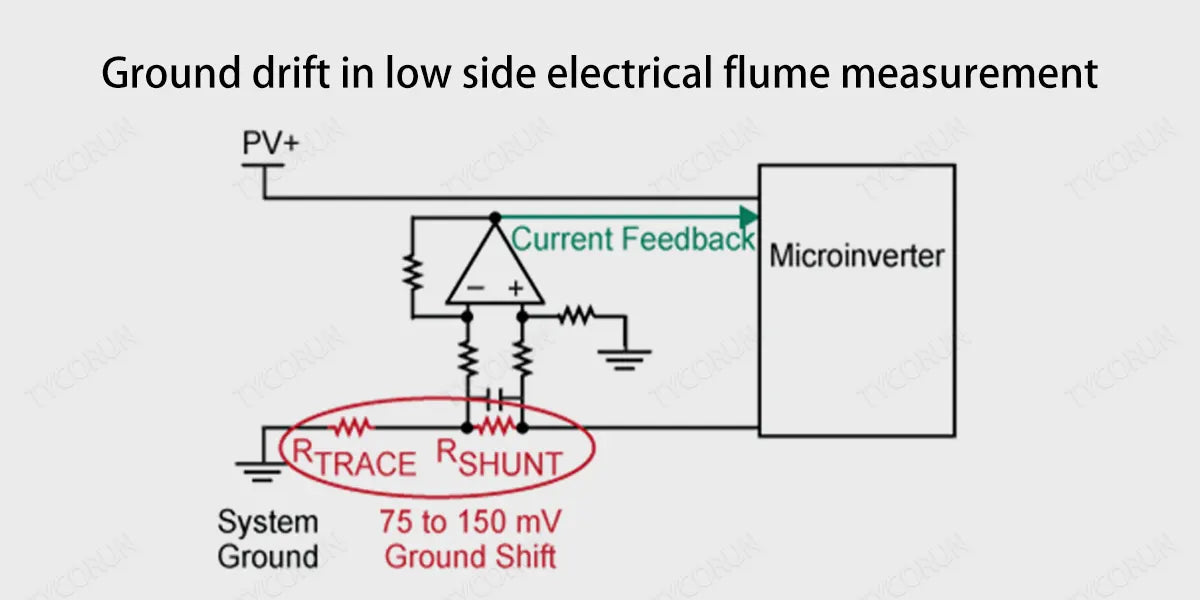
Ground interference in low-side shunt sensing
The use of low-side shunts in high-throughput systems often results in ground interference. Depending on the size of the shunt, high current conditions can introduce significant instability in the ground plane and affect the precision circuits in the micro-inverter. A 25A PV panel can generate 100mV+ interference, which in turn affects local sensitive control and feedback devices and leads to unwanted operational or reference errors.
In a suboptimal PCB layout, the ground shift caused by the shunt can cause the critical MPPT(Maximum Power Point Tracking) voltage measurement to lose its accuracy and affect the integrity of the communication signal. To mitigate these effects, the ground reference needs to be properly isolated to prevent metastability in the micro-inverter sensing circuit and controller.
A smaller shunt resistance reduces ground interference and introduces power loss / heat into the system, but at the same time reduces measurement accuracy at low current levels. The selection of shunt will affect the deviation error.
Taking a 1 Mω shunt, 1A PV current, and a 50μV bias operational amplifier as an example, the error may increase by 5% at low current. This error is exacerbated if the micro-inverter is subject to a significant temperature rise.
High-side sensing solutions do not introduce these grounding issues and guarantee high accuracy throughout the photovoltaic panel current and temperature range. The comparison of low side sensing, high side sensing and high side Hall effect sensing is as follows:
|
Low side sensing |
High side sensing |
High side Hall effect sensing |
|
|
BOM quantity |
Medium |
Medium |
Low |
|
Complexity |
Low |
Medium |
Low |
|
Accuracy |
Medium to high |
High |
High |
|
Short circuit detection |
Not support |
Yes |
Yes |
|
Power consumption |
Low to medium |
Low |
Low |
|
Design dimensions |
120 mm² |
500 mm² |
9 mm² to 100 mm² |
Related posts: off grid solar batteries, UPS power supply, top 5 solar microinverter companies in the world


