

Generally speaking, two inverters can be connected in parallel to increase the power. If the performance parameters of the two inverters are the same, the power can be expanded by directly connecting the two inverters in parallel, but various parameter matching and protection measures need to be paid attention to. This article will introduce you to the principles of parallel connection of inverters and the methods to avoid circulating current.
Main content:
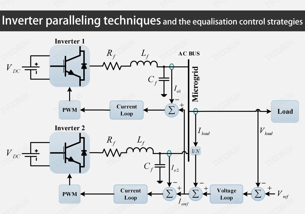
1. Principle of inverter paralleling
The equivalent circuit model of the inverter parallel structure is shown in the figure below.

In this figure, U1 and U2 are the fundamental wave components contained in the SVPWM voltage wave output by the two inverters respectively, U11 and U22 are the respective output terminal voltages, and Uo is the parallel node voltage (i.e. load voltage; C1, C2, L1 , L2 represents the output filter inductance and capacitance of the two inverters respectively, the filter inductor connection resistance and its internal resistance are represented by rLI and rL2 respectively, and r1 and r2 represent the parallel connection (wire) resistance, Z0 common load.)
To simplify the analysis, ignore the effects of rL1 and rL2, r1 and r2. According to the figure, the following basic circuit equations can be listed:

In this equation, Ic1 and Ic2 are the currents flowing into the capacitors C1 and C2 respectively. When C1=C2=C, L1=L2=L, it can be deduced:

The following basic conclusions can be drawn from this equation:
- When U1=U2, IL1=IL2=I0/2+jꙌCU0, the two inverters share the load current equally.
- When U1≠U2, IL1=IL2 is composed of load current component and circulating current component, and the load current sharing between the two inverters is unbalanced.
- When U1 and U2 are in the same phase, the phases of the circulating reactive components of different amplitudes are different. The circulating current of the home solar inverter with high voltage is capacitive, and the circulating current of the inverter with low voltage is inductive.
- When the amplitudes of U1 and U2 are equal, the circulating current component whose phase is ahead of the former is a positive active component (active power is output), and the circulating current component whose phase lags behind is a negative active component (active power is absorbed).
- When U1 and U2 have different amplitudes in different phases, there are both reactive components and active components in the circulating current component.
We can see that when multiple modules are running in parallel, due to the differences in the external characteristics of each module or the difference in the external loop voltage given value, there will be differences in the current between the modules, and even inconsistent working conditions, resulting in large circulating currents between parallel voltage source PWM inverters, which affects the stability of the entire system.
For this reason, the inverter modules are not allowed to be directly connected in parallel, and certain current sharing measures need to be taken to suppress the generation of circulating current.
2. Current sharing control strategy for parallel inverters
If the frequency, phase and amplitude of the inverter output voltage cannot be guaranteed to be the same, circulating current will occur, causing great system losses, and even causing system collapse and power supply interruption. How to take effective circulation suppression measures is the key to realizing the operation of parallel inverter systems.
For parallel connection of switching converter modules, the basic design requirements are:
- The current carried by each module can be automatically balanced to achieve current sharing;
- In order to improve the reliability of the system, when the input voltage and/or load current change, the output voltage should be kept stable and the current sharing transient response should be good.
The parallel connection technology of inverter power supply can realize N+1 (N=1, 2, 3...) redundant parallel operation mode. When any module in the system fails due to fault, the remaining N modules can still continue to provide with 100% load power, fault-tolerant redundant power can be obtained at the expense of smaller power redundancy, which greatly improves the reliability of the system. Parallel redundancy control is the preferred solution to achieve high reliability and high power supply for home solar power system.
Under normal circumstances, the output resistance of each parallel module is constant, and the unbalanced output current is mainly caused by the unequal output voltage of each module. The essence of current sharing is to adjust the output voltage of each module through the current sharing control circuit, thereby adjusting the output current to achieve the purpose of current sharing.
At present, the current sharing control strategies for parallel operation of inverters (such as 2000w inverter or 3000w inverter) mainly include: current detection loop method; master-slave parallel control method, decentralized logic control method, and external characteristic droop parallel control method.
① Current detection loop
Take dual parallel connections as an example, as shown in the figure below:

When the output voltages of the two channels deviate slightly, there will be a deviation voltage. The amplitude deviation of the inverter voltage and current vector is as shown in the figure:

If the output voltages of the two channels are slightly out of phase, it will cause the output voltages of the two channels to be basically vertical, as shown in the figure:

Minimizing the amplitude and phase deviation of the output voltages of the two channels will reduce the deviation voltage and thus the circulating current. It can be seen from the figure that the secondary currents of the current transformers of channel 1 and channel 2 are the currents flowing through the sampling resistors R1 and R2 respectively. The current detection closed loop formula is:
IR1R1+IR2R2=(I1-IT)R1+(I2-IT)R2=0

Generally, R1=R2, then IT=(I1+I2)/2 reflects the load current mean and current deviation, which are separated into active power and reactive power components, and used to adjust the voltage phase and voltage amplitude respectively. Thereby achieving the balance of active power and reactive power.
② Master-slave control
In the master-slave control structure, a special voltage stabilization and current sharing control module (master module) is set up in the system. The slave module is an inverter module with current follower properties. It can work well under various load conditions and dynamic processes. Ground current sharing is achieved, and power redundancy can be achieved between the modules.
The voltage loop of the main module control system is adjusted, and its output voltage signal is used as the given signal of the inner loop current. The current of the slave module is based on the output current of the master module and follows the output current of the master module, without the need for a phase-locked loop circuit to achieve synchronization.

Each module in the master-slave parallel control mode has an independent control loop and a dedicated current distribution loop, which can accurately adjust the output voltage and share the load power at the same time. The control structure is simple and the accuracy is high. But there are still some shortcomings:
- The system has a certain dependence on the main module. Once the main module fails, the slave module will not be able to work normally and the entire system will be paralyzed. The system does not achieve true redundancy and has low reliability.
- The master-slave control method requires interconnection lines between modules. The control performance depends largely on the speed of communication. It has some restrictions on the distance between distributed power supplies and may also introduce noise, so its application has certain limitations.
③ Maximum current parallel control
In order to make up for the shortcomings of the master-slave control method and eliminate the system's dependence on the master module, the maximum current parallel control method adopts the automatic master-slave control method.
The master module and the slave module are not set manually in advance, but are automatically set according to the current size. That is, when parallel modules are running, the module with the largest output current will automatically become the master module, and the other modules will be slave modules. The control block diagram based on the maximum current parallel control method is shown in the figure below.

The design of control parameters is no different from the master-slave control mode, but a current comparator is used between each module of the control system to determine which module serves as the master module. The master-slave module switches alternately according to the size of the output current.
The maximum current automatic current sharing method can avoid the impact of the main module failure on the system. It can not only ensure the accuracy of current sharing, but also make up for the shortcomings of the master-slave parallel control method. But it also produces the following shortcomings:
- Since the identity of the master-slave module in the system is uncertain, the alternation of the master-slave module will cause alternating fluctuations in the output voltage, affecting the stability and accuracy of the output voltage;
- Usually the voltage given value has a certain range. However, when the current sharing circuit adjustment reaches the limit, the inverter module can only exit the current sharing adjustment; during the current sharing process, the current of the master and slave modules will also change repeatedly, and low-frequency oscillation may occur.
④ Distributed logic control
In the decentralized logic control structure, the control rights of the system are decentralized and independent, the current sharing control is dispersed in each module, and information is exchanged through the signal interconnection lines between modules. All modules are the same and can truly achieve redundancy, ultimately allowing each unit in the system to work independently.
In the decentralized logic control structure, the most commonly used current sharing control strategy is the mean current sharing control strategy. The mean current sharing control strategy uses the phasor relationship between the output circulating current and the reference voltage to adjust the reference voltage of the voltage closed loop (current circulation or power circulation) to the inverter module.
The average current sharing control strategy determines that the current sharing control can only be adjusted once per voltage cycle, so the dynamic response of this control strategy is slow. When there is a difference in the phase and amplitude of the reference voltage before the inverter module is connected, it leads to a large circulating current between the inverters during several cycle times after the connection and causes an overcurrent, and the mean-value equal-current control has poor suppression characteristics of the harmonic circulating current.
Related posts: inverter shops near me, global top 10 best solar inverter brands, working principle of inverter


