

In the power grid system, the production and consumption of electricity need to be kept in step. However, due to the intermittency and randomness of wind power and photovoltaic power, their power generation status is unstable and uncontrollable, and large-scale storage cannot be carried out.
Large-capacity energy storage technology can not only smooth the power fluctuations of wind power and photovoltaics, promote their large-scale consumption and access, but also perform frequency and peak regulation on the power grid to improve the ability of the power grid to operate safely and stably. This is a major step for the development of wind power and photovoltaics.
The research results show that in some application scenarios of medium and high power, the heat dissipation method of thermally conductive interface materials and forced air cooling are a good choice. The good filling effect of the thermally conductive interface materials can improve the heat dissipation capacity of LFP battery modules and provide storage solutions. It can provide a theoretical basis for the design of battery module thermal management system.
Main content:
1. Heat dissipation methods of energy storage modules
As the energy carrier of container-level energy storage power stations or home solar power system, the research and development design of large-capacity battery modules includes the following key technologies: system integration technology, structural design technology, electronic and electrical design technology, thermal design technology, and safety design technology. Among them, thermal design technology is an extremely critical step in the development of large-capacity energy storage battery modules.
The temperature of the battery and the uniformity of temperature between individual cells within the PACK are key factors affecting its performance and life. For the best batteries, you can also refer to the battery stores near me. Therefore, a good thermal management strategy can effectively control the maximum temperature of the battery to ensure that the battery is within a suitable temperature range and balanced. The temperature between cells provides a strong guarantee for the efficient, safe and long-life operation of energy storage batteries.
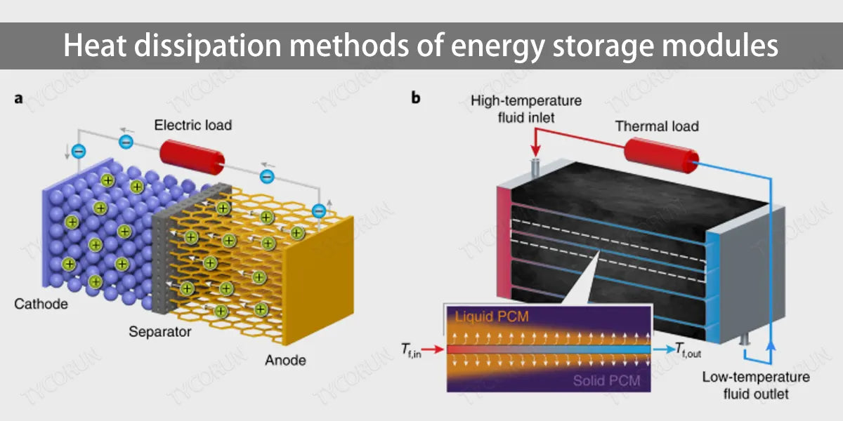
According to different heat transfer media, the heat dissipation and cooling methods of battery modules can be divided into natural cooling, forced air cooling, liquid cooling and phase change cooling. The basic principles of the three cooling methods of natural cooling, forced air cooling and liquid cooling are that the cooling medium flows through the surface of the heating device.
Due to the temperature difference between the two, heat transfer occurs between the two and the heat of the heating device is transferred. The cooling medium does not undergo a phase transition during this process; phase change cooling is when the cooling medium undergoes a gas-liquid phase transition in the cold plate. During the transition process, it can absorb heat and transfer the heat of the heating device in contact with it to cool the main body.
The following table compares four cooling methods.
|
Heat dissipation method |
Natural cooling |
Forced air cooling |
Liquid cooling |
Phase changing cooling |
|
Use |
Easy |
Easy |
Moderate |
Easy |
|
Installation |
Easy |
Easy |
Moderate |
Moderate |
|
Cooling capacity |
Above ambient temperature |
Above ambient temperature |
Above ambient temperature |
Above ambient temperature |
|
Uniformity |
Low |
Low |
High |
Low |
|
Tightness |
Difficult |
Difficult |
Easy |
Easy |
|
Maintenance |
Low |
Low |
Moderate |
Moderate |
|
Cooling principle |
Natural convection of air |
Forced convection of air |
Forced convection of liquid |
Forced convection of phase changing |
|
Convective heat transfer coefficient/[w·(m²·K)-l] |
5~25 |
25~100 |
500~15000 |
2500~25000 |
|
Surface heat flow density/(w·cm-2)(10℃ difference from ambient temperature) |
0.005~0.025 |
0.025~0.150 |
0.500~15.000 |
2.500~25.000 |
As we can be seen from the table, in terms of cooling capacity and cooling efficiency, liquid cooling and phase changing cooling are significantly higher than natural cooling and forced air cooling. However, taking into account of the conditions of battery charging and discharging, and environmental conditions, product structure and function design, and the requirements of power consumption and cost, natural cooling and forced air cooling are more suitable for energy storage battery modules.
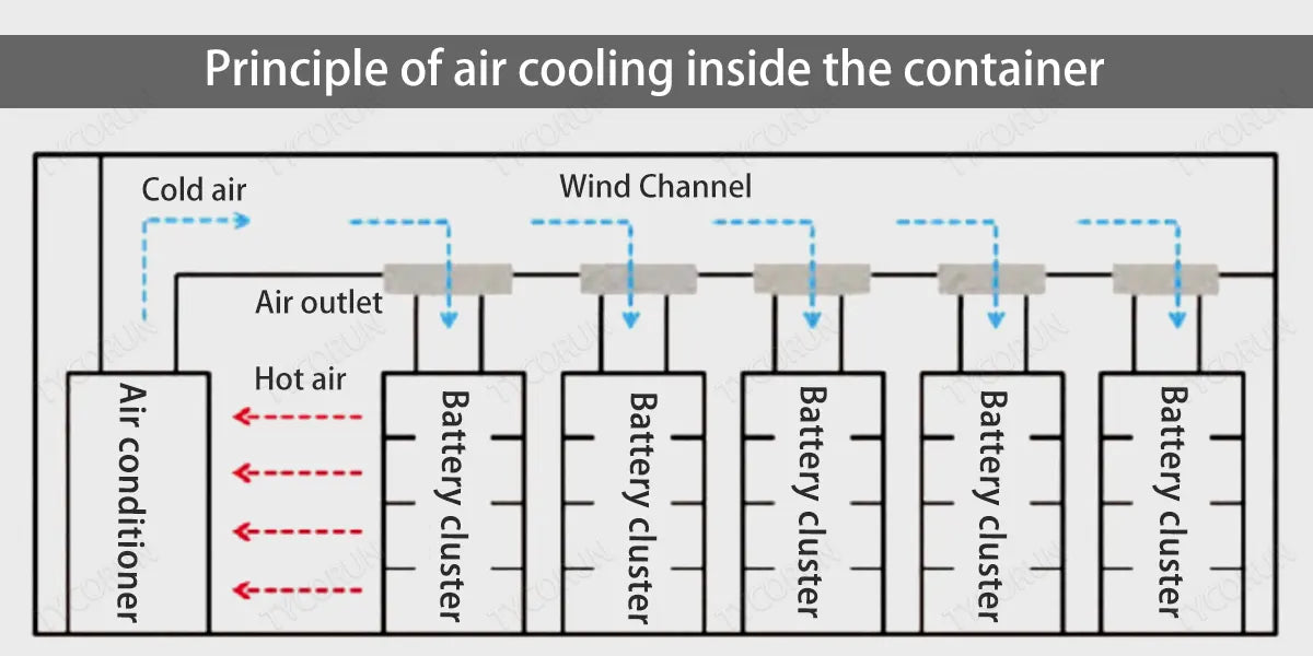
This is because cabin-type energy storage systems are generally equipped with air-cooled air conditioners and corresponding air duct designs. After the air conditioner is running, cold air will continuously enter the battery box through the special air-cooled channel, taking away the battery such as 12 volt 100ah deep cycle lithium battery or 12v 200ah deep cycle battery for charging and discharging. The heat released and the heated air will also be sucked into the interior of the air conditioner as the air conditioner operates, as shown in the figure below.
In this way, hot and cold air circulates alternately, and the ambient temperature inside the cabin is reasonably controlled to ensure that the battery environment is suitable. At the same time, through the open air conditioning communication protocol, the temperature of the battery is used to control the start and stop of the air conditioner to achieve an efficient and energy-saving air conditioning operation plan.
2. Solutions to heat dissipation and thermal conduction of energy storage module
Under operating conditions of low rate, the heat emitted during battery charging and discharging can be taken away by the natural flow of air. However, in some medium and high-rate products, due to the large charge and discharge current, natural cooling alone cannot remove the heat inside the module.
Dissipating it quickly and effectively can easily cause heat to accumulate inside, which will affect the cycle life of the battery core and even cause safety hazards. Therefore, the heat dissipation method of forced air cooling is more suitable for the application scenarios of medium and high-rate energy storage products.
The internal structure of the forced air cooling module is generally as shown in the figure below: an axial flow fan is placed on the front panel of the sheet metal battery box. There are several battery packs located inside the battery box at the bottom of the box. The top of the rear part of the box is designed with grid-shaped vents.
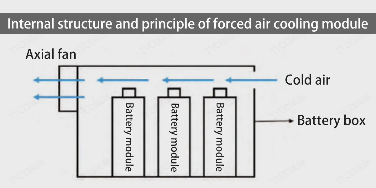
After the axial flow fan is running, the cold air enters the inside of the box through the rear grille-shaped ventilation holes and passes over the busbar surface on the top of the battery pack in turn. The bus bar and the battery poles are integrated by laser welding.
During the charging and discharging process, the location of the battery poles is where the current gathers and is also the area where the most heat is generated. And the bus bar is generally made of aluminum or copper. Both materials are good conductors of heat. The thermal conductivity of pure aluminum is 237 W/(m·K) and that of pure copper is 401W/(m·K).
Therefore, as the cold air sweeps across the bus bar, the heat at the end of the pole will be dissipated into the air through the bus bar, and will eventually be sucked to the outside of the box by the fan along with the flow of air, thereby achieving internal cooling and heating.
Under some more severe working conditions, the heat dissipation at the battery pole end can no longer meet the usage requirements, and other heat dissipation methods need to be assisted to improve the overall heat dissipation efficiency of the system.
The battery pack is usually located at the bottom of the box, and the box material is mostly cold-rolled steel plate, which is also a good conductor of heat. Through the contact between the bottom of the battery and the box, the heat inside the battery is conducted to the surface of the box, and then further heat is exchanged with the external environment through the surface of the sheet metal box to achieve the purpose of auxiliary heat dissipation at the bottom of the battery.
However, during the actual assembly process, the slight unevenness of the bottom of the battery pack and the flatness error at the bottom of the box will cause the battery pack and the box to not be in close contact, that is, the battery pack and the bottom of the box will not be in close contact. There will be small air gaps.
Air is a poor conductor of heat, and the air gap will increase the thermal resistance between the battery pack and the box, affecting the heat dissipation effect, as shown in the figure below.
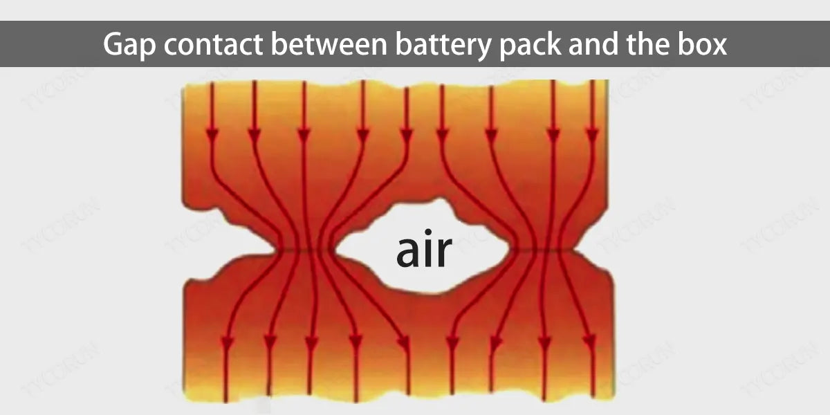
In order to solve this problem, it is urgent to find a solution that can fill the gap between the two contact planes, reduce the thermal resistance of the target original to the environment, create a low thermal resistance convection path between the bottom of the battery and the box, and ensure uniform contact and higher heat transfer efficiency.
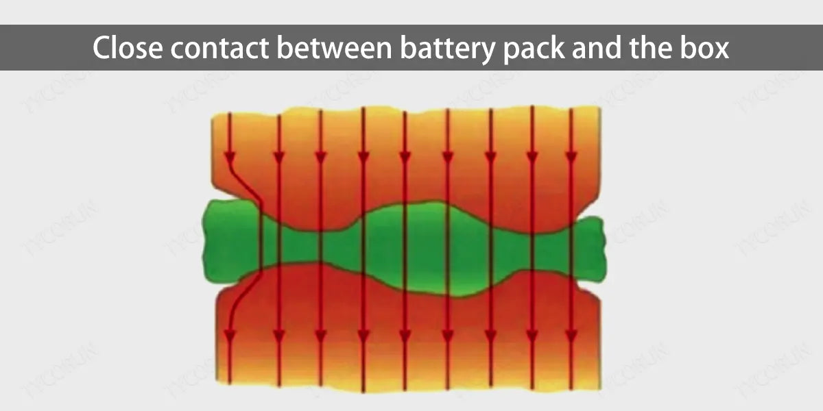
Among all the solutions, thermal interface materials have the advantages of high thermal conductivity and low interface thermal resistance. At the same time, high deformation and good compressibility allow them to exclude the air between the contact surfaces under a certain pressure and fully fill the gap between the contact surfaces.
The rough area improves the heat conduction effect between the contact surfaces, and its good filling performance can conduct the heat from the heating end to the heat dissipation end, as shown in the figure below.
3. Classification of thermal interface materials
Thermal interface materials come in two different forms: solid and liquid, which can meet the performance requirements of diversified products.
- Liquid thermal interface materials: Liquid thermal interface materials are generally thermal paste, thermal glue, etc. These thermally conductive materials in liquid form can be applied directly to the target component and serve as an adhesive to the heat sink. At the same time, these materials can also be mixed with ceramic fillers, metal or metal oxide fillers to obtain higher thermal conductivity.
- Thermal conductive silicone gasket: Thermal conductive silicone gasket is a thermally conductive interface material synthesized through a special process using silica gel as the main base material, adding various auxiliary materials such as temperature resistance, thermal conductivity and insulation materials.
Unlike liquid thermal materials, preformed solid thermal silicone gaskets are also very simple to use and can be die-cut to the required size. They are suitable for joining with heat sinks on planar components or directly attached to the housing. The pasting of thermally conductive silicone gaskets can be integrated with the automated assembly process to further improve production efficiency and automation.
Related posts: Top5 home energy storage companies in China, charging temperature, battery cooling system


