

From the perspective of the strategic goals of countries around the world, the development of electric vehicles has been generally established as an important way to ensure energy security and transition to a low-carbon economy. The common feature of the action plans of various countries is that the government directly intervenes, organizes the joint promotion of energy, transportation, manufacturing and other departments, and adopts a multi-pronged approach to R&D investment, industrial layout, and preferential policies to promote the intersection of multiple industries such as vehicles, power batteries, and smart grids. Integration and comprehensive development to create an emerging strategic industrial chain. Electric vehicles include pure electric vehicles powered by power batteries, hybrid electric vehicles with coexistence of electric motors and internal combustion engines, and fuel cell electric vehicles powered by fuel cells. These three types of electric vehicles all use one or more motor drive systems to convert electrical energy. For mechanical energy, the braking energy of the brake is recovered, so as to double the energy utilization rate. Therefore, the motor drive system is considered to be one of the three core technologies of electric vehicles. The requirements of electric vehicles for the motor drive system can be summarized as high power density, high efficiency in the whole working area, high performance (including low speed and high torque, wide constant power range, high dynamic response), high environmental adaptability and low cost. The differences between the automotive motor drive system and the general industrial motor drive system are as follows.
(1) The significance of the high power density of the vehicle motor drive system is not only to meet the compact space constraints of the vehicle, but more importantly, it is the most important way to reduce the system cost. Therefore, the degree of saturation of the automotive motor design is high, which leads to the problem of parameter nonlinearity that must be dealt with in the motor control. To this end, automotive motor controllers seek to improve the utilization rate of 1GBT (double-sided cooling), component integration and efficient thermal management.
(2) In terms of efficiency, the electric motor drive system for electric vehicles has a wide working area, so it is necessary to carry out the corresponding efficiency optimization design in the entire working area. In terms of power performance, low-speed and high-torque electric vehicles require close integration of motor design and control to achieve maximum torque-to-current ratio control according to the parameters of the motor; The control margin of the inverter is very small, so it is a key technology to correctly track the d and q-axis currents in the field weakening control to widen the field weakening ratio (ie wide constant power region).
(3) Another feature of the vehicle motor drive system is that the use environment is harsh: if the ambient temperature is from -40°C to +125°C, the maximum vibration is even greater than 10g, and the environmental adaptability requirements increase the high power density of the vehicle motor drive system. difficulty.
According to the requirements put forward in the application of electric vehicles, the technical development trend of electric vehicle motor drive system can be summarized as: permanent magnet high efficiency, power electronic integration and electromechanical integration.
Vehicle motor drive converter technology, the drive converter of vehicle motor mostly adopts three-phase full-bridge topology [as shown in Figure 1(a)] or parallel three-phase full-bridge topology with front bidirectional DC/DC [such as Figure 1 (b)], the main circuit structure is relatively simple. In the research of the new type of vehicle converter, in order to increase the voltage to the motor terminal (thus increasing the output power of the motor drive system at high speed), the DC support capacitor which is bulky and has poor high temperature performance in the vehicle converter was removed. Research based on current source inverter (CSI) converter. It is worth pointing out that the research focus of automotive inverters has been focused on power electronics integration for many years. It can be predicted that the automotive motor inverter production line will break the boundaries of power semiconductor packaging and electronic assembly, and extend the manufacturing of power electronic equipment to Power semiconductor packaging stage.
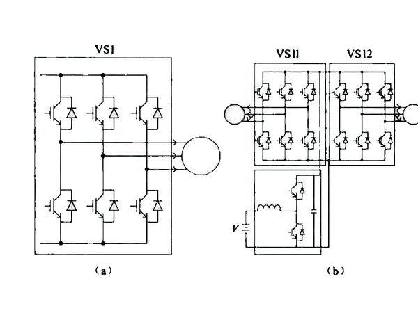
Figure 1 Typical topology of automotive motor drive converter
The power electronic integration technology is reflected in the automotive converter as follows:
(1) Multiple on-board DC/AC and multi-channel DC/DC converters are integrated into the same box, and some busbars and DC support capacitors are shared, which reduces the amount of cables and improves the external electromagnetic radiation;
(2) For a single converter, use high power density IGBT modules or even custom modules (for example, a GBT module of the Prius 2010 controller includes 6 inverter half-bridges and 1 boost half-bridge) to integrate the DC busbar with capacitors Since then, and research the overall efficient heat dissipation technology of the converter
(3) The automotive IGBT module uses a 175°C trench gate field terminated GBT chip. Therefore, in the electromagnetic design of the module, the multi-chip and linkage static current sharing and low EM loop design technology are considered; in the module heat dissipation design, research and development Direct cooling and double-sided cooling technology. It is particularly worth pointing out that since the withstand voltage of SC is 10 times that of S and the thermal conductivity is 3 times that of Si, the reverse recovery loss of SiC diodes can be reduced by 66%. With the gradual commercialization of 600V and 1200V SiC diodes, S-based Modules in hybrid packaging of GBT and SC diodes are also the focus of research;
In electric vehicle drive applications, the main function of the DC bus support capacitor is to provide ripple current. The film capacitor using the self-protected spray electrode technology has high reliability. The integration of passive components in the main circuit of the rectifier.
At present, the research and development of IGBT module packaging, capacitor and busbar integration, and high power density automotive converters have been carried out. As shown in Figure 2, the 1200V/450A direct cooling IGBT module adopts the EeonoPaek+ package form. Based on the chip layout and interconnection design, the pin-rib layout of the copper substrate of the module is optimized to make the maximum temperature at the IGBT chip of the module more balanced and flowing. The flow rate of the channel is uniform, thereby reducing the thermal resistance of the module by 30%.
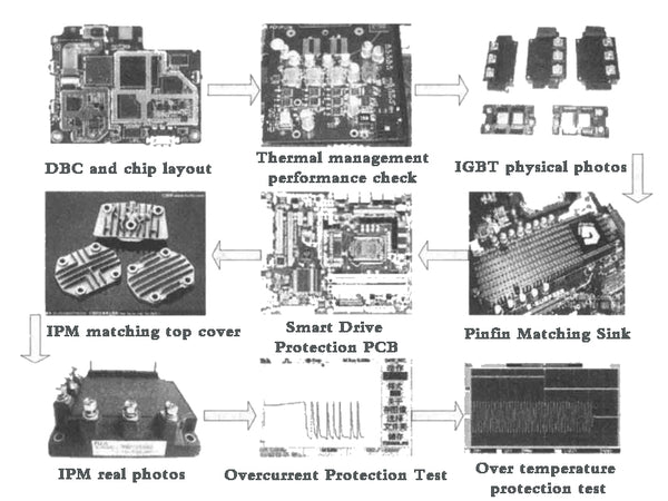
Figure 2 1200 V/450 A direct cooling IGBT module


