


main content:
The electrical equipment of an electric vehicle is directly installed on the vehicle chassis, each electrical equipment has an independent current loop, and there is no direct electrical connection with the chassis. The entire high voltage system is a closed electrical system insulated from the chassis. The insulator is relative to the conductor. In the DC power system, the physical quantity that quantitatively describes the insulating performance and conductivity of a medium is resistance. The resistance of the conductor is small, and the resistance of the insulator is large. The resistance of the insulator characterizes the insulation performance of the medium. The greater the resistance, the better the insulation performance, and vice versa, so the resistance is also called insulation resistance. In the high-voltage electrical system of an electric vehicle, the insulation resistance of the positive lead cable and the negative lead cable of the power supply to the chassis is used to characterize the insulation performance of the electrical system.
Insulation monitoring technology is an important technology related to personal safety. According to the relevant regulations of electric vehicles and people's standards, under the condition that the maximum working voltage is less than 660V/AC or 1000V/DC, and the vehicle mass is less than 3500kg, the high-voltage safety requirements for electric vehicles are as follows:
①The safety voltage of the human body is lower than 35V;
②The maximum value of the product of electric shock current and duration should be less than 30mA;
③In order to ensure the insulation safety of the on-board battery of the electric vehicle, the insulation resistance between the battery pack and the vehicle body must be measured in real time during the operation of the vehicle, and the alarm can be timely when there is a problem.
It can be seen that the measurement of insulation resistance is of great significance for the application of power battery packs. At present, the detection methods of insulation resistance mainly include the following.
1. Megohmmeter measurement method

A megohmmeter is a common electrical measuring instrument scaled in megohms. Most of them are powered by hand-cranked generators, so they are also called "shake meters". The megohmmeter is mainly composed of a hand-cranked generator and a magnetoelectric ratio meter.
When the megohmmeter is working, it first generates high-voltage alternating current by shaking the handle to drive the hand-cranked generator, and then output the DC high voltage used for measurement through the diode rectification, and then use the magnetoelectric ratio meter to measure the current ratio in the voltage coil and the current coil, and the pointer indicator indicates the scale of the resistance value. It can be seen that the working principle of the megohmmeter is to first excite the device or network under test through a voltage, then measure the current generated by the excitation, and then use Ohm's law to obtain the specific value of the resistance.
The main disadvantages of megohmmeters are as follows:
①When measuring, the handle must be driven to drive the generator and kept within a certain speed range to maintain normal voltage output.
②The voltage level of the same megohmmeter is small, and the range is small;
③ The hand-cranked megohmmeter indicates the reading by the needle, but due to its non-linear scale, the measurement error and reading error are large;
④ It is impossible to output a relatively stable voltage, and the operation is complicated;
⑤ The reverse impulse current of the pointer type megohmmeter is large when it is turned off, and the pointer may be damaged if it is improperly operated.
2. AC signal injection method

The AC signal injection method is to inject the AC signal into the DC system, and monitor the insulation state of the system through the corresponding comparison calculation.
This method injects a low frequency AC signal into the DC system through a 2Hz signal generator. If there is an insulation fault in the system, the AC signal will flow out from the grounding line and form a loop with the signal source through the ground. At the same time, the phase-shifting technology is used to amplify and filter the signals collected by the transformers on each load, and then compare them with the standard synchronous signal through the phase comparison circuit. After filtering out the interference of the capacitors, the real resistive impedance can be obtained, so as to accurately calculate the actual grounding resistance of each load and find out the insulation fault.
The disadvantage of this method is that the additional AC signal injected into the DC system is greatly disturbed by the distributed capacitance, and it will also have a certain impact on the DC system. Distributed capacitance refers to the capacitance, in addition to the capacitor, due to the distribution characteristics of the circuit. Distributed capacitance often has no specific form. For example, there is a certain capacitance between two adjacent turns in a coil, between two discrete components, between two adjacent wires, and between various parts within a component. Its influence on the circuit can be equivalent to adding a capacitor in parallel to the circuit, and this capacitance value is the size of the distributed capacitance. Since the impedance of the distributed capacitance is inversely proportional to the frequency, the resolution of the system will be reduced when the low frequency signal injection method is used. In addition, this method also puts forward higher requirements for the stability of the low monkey signal, and needs to increase the AC signal generation system, which increases the cost.
3. DC voltage insulation measurement method

DC voltage insulation measurement is generally completed by measuring insulation resistance, the principle of which is shown in Figure 1.
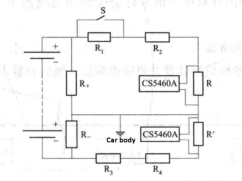
In Figure 1, R1, R2, R3, and R4 are 500kΩ resistors, respectively. The higher resistance value ensures that the insulation level will not be artificially lowered during the measurement. R+ and R- are the insulation resistance of the positive and negative electrodes of the power battery pack to the vehicle body respectively; R and R' are voltage divider resistors of about 200Ω. Since the resistance of these two resistors is very different from 500kΩ, the AD conversion chip CS5460A can obtain a millivolt (mV) level analog signal.
When the switch S is in the off state, the voltage across R+ and R- can be obtained through the CS5460A measurement chip, and the following equation is obtained:
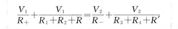
(1-1)
In the formula:
V1—the voltage of the positive bus bar to the ground when the switch S is disconnected, V;
V2—When the switch S is turned off, the voltage of the negative bus bar to the ground, V.
Similarly, when the switch S is closed, another equation can be obtained:

(1-2)
In the formula:
When V'1-S is closed, the voltage of the positive busbar to the ground, V;
When V'2-S is closed, the voltage of the negative bus bar to the ground, V.
Since the resistance values of the series resistors R1, R2, R3, R4, R and R' are known, the values of R+ and R- can be solved immediately by combining the formula (1-1) and the formula (1-2). This is also the most commonly used insulation resistance detection method.
Since the switch S is a switch tube (MOSFET), and the control signal of the switch S is in common with the vehicle body. Therefore, during the insulation measurement, the large current signal of the electric vehicle will generate a certain disturbance signal, which will cause the switch-off of the MOSFET (MOSFET) to be disturbed by the AC signal, which will have a great impact on the calculation of the insulation resistance and seriously affect the measurement accuracy of the insulation resistance.
In practical applications, considering the cost and process issues, the signal sampling in the insulation resistance measurement scheme and the current and voltage sampling in the power battery management system (BMS) share a chip (ie CS5460A). CS5460A is an integrated chip produced by CRYSTAL for measuring parameters such as voltage, current, power and energy. It has a 24-bit A/D converter inside, which can measure voltage in real time. However, since the measurement signal of the CS5460A measurement chip is at the millivolt (mV) level, the width of the accepted measurement signal is not high, and the sampling of the voltage will be affected by the high-voltage side of the power battery pack, and its measurement accuracy needs to be improved.
4. Active online insulation monitoring method
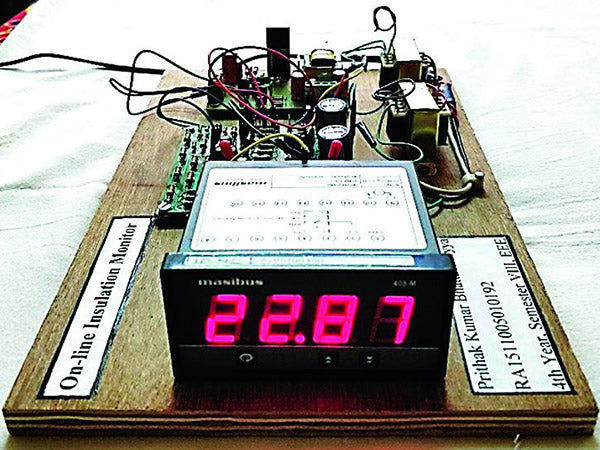
The active online insulation monitoring device for electric vehicles mainly completes three main functions: measurement, communication and warning.
The device takes the MC9S12D64CPV chip as the core, through the control of the linear optocoupler and the chip PWM, and uses the method of comparing and following to detect the voltage and current of the positive and negative electrodes of the vehicle battery pack to the ground, and then obtain the resistance value of the insulation resistance. In addition to CPU, the system also includes sampling circuit, key circuit, relay control circuit, indicator light, power supply circuit, CAN communication circuit, PWM shaping and transformer control circuit and other components. The specific functions of each module are as follows.
(1) Sampling circuit. According to the different sampling objects, the main working range of the sampling circuit has two parts. One part is to sample the current injected by the system into the insulation resistance and the voltage divided by the positive and negative insulation resistance through the sampling resistance, and the other part is to sample the total voltage of the battery.
In the measurement of the injection current of the insulation resistance and the voltage divided by the positive and negative insulation resistance, first obtain the measurement signal through the sampling resistor, and then read the corrected signal through the AD sampling channel of the CPU after a series of filtering, following, comparing and amplifying links. In this process, it should be noted that the sampling resistor, the subsequent comparison amplifier circuit and the CPU all need to share the ground to ensure accurate sampling.
Considering the influence of the total battery voltage transient on the accuracy of insulation resistance measurement, a special voltage measurement chip should be used to measure the total voltage of the power battery pack. The measurement signal is isolated by the linear optocoupler and sent to the voltage measurement chip, and finally read through the AD sampling channel in the CPU.
(2) Button circuit. The key circuit is mainly used to facilitate debugging and monitoring. Since there is a certain time interval between two insulation monitoring, during monitoring, if you want to know the insulation resistance value of the vehicle at that time, it can be achieved through the key circuit without waiting.
(3) Relay control circuit. Since there is a common ground between the CPU and the car body, in the control part of the relay, in order to ensure that the signal is not disturbed by the vehicle body and an error occurs, the control signal output by the CPU is isolated by light accident to prevent the malfunction of the relay.
(4) Indicator light.
(5) Power circuit. It is powered by the 24V power supply on the vehicle. According to the actual needs of each system component, the non-isolated power supply and the isolated power supply are obtained through the power converter, and outputs of different voltage levels are provided to drive each functional module in the system.
(6) CAN communication circuit. For communication between vehicle controller and battery management system (BMS), according to actual needs, the calculated results of the insulation resistance and insulation level of the positive and negative poles of the power supply to the vehicle body can be sent to the vehicle controller to optimize driving.
(7) PWM shaping, transformer control circuit. Through the parameter setting inside the CPU, the PWM signal with the set frequency and duty ratio is shaped by the op amp, and then the transformer is controlled. The overall control of the system adopts a single-chip measurement and control system to complete the control and measurement of the above-mentioned various circuits, and integrates the three functions of measurement, communication and warning to form a complete active insulation monitoring device.


