main content:
In a common battery module composed of cylindrical batteries, several battery cells are generally connected in series and parallel to form a battery module, and then according to the power output requirements of electric vehicles, the battery modules are arranged in a predetermined arrangement to form a battery assembly box. There are three common battery arrangements: in-line arrangement, fork arrangement and trapezoidal arrangement (Figure 1).
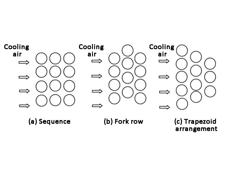
Figure 1 - Battery arrangement
In-line arrangement is to arrange the batteries in the battery box in sequence, and the cooling airflow entering from the outside will pass through the gaps between the batteries unimpeded. The advantage is that the flow resistance is small; the disadvantage is that the airflow is not easily disturbed to generate turbulent vortices, the effective contact area with the battery body is small, and the convective heat transfer is small, so the cooling efficiency is not high, and it is generally not used.
The fork row arrangement is to arrange the battery modules of two adjacent layers in the battery box in a staggered manner along the air circulation direction. After the cooling gas entering from the outside passes through the gap between the cells, it will blow directly on the surface of the next layer of cells, then bypass the surface of the cell body and flow to the gaps on both sides of the cells. The advantage is to increase the disturbance of the airflow through the battery, improve the convective heat transfer coefficient on the surface of the battery, reduce the thermal resistance, and improve the heat dissipation effect; the disadvantage is that the flow resistance loss is large.
The trapezoidal arrangement reduces the number of cells along the airflow direction, gradually reduces the cross-sectional area of the channel along the airflow direction, and gradually increases the wind speed, thereby increasing the heat transfer coefficient. Adopting the trapezoidal arrangement, although the temperature of the gas flow gradually increases along the flow direction, the heat transfer coefficient increases due to the gradual increase of the wind speed, which balances the heat dissipation effect of the upstream and downstream, so that the temperature of the upstream and downstream of the battery pack can be basically controlled at a relatively uniform level.
With the increase of ambient temperature, the increase of battery size and the increase of battery power requirements, the conventional air-cooled cooling system can no longer meet the cooling requirements. For lead-acid batteries, Choi and Yao pointed out that relying on natural convection or forced convection is not an effective solution to their temperature rise. For Li-Po batteries, due to the small thermal conductivity of polymers, only relying on air-cooled heat dissipation systems cannot effectively solve the heat dissipation problem. When Nelson et al. studied Li-ion PNGV (partnership for a new generation of vehicles) batteries, they found that when the battery is in a warm environment, it is difficult to reduce the temperature of the 66℃ battery below 52℃ by using air-cooled heat dissipation. Through numerical simulation analysis, Chen et al. found that after the intensity of forced convection increased to a certain extent, the balance of temperature distribution of Li-ion batteries was not fundamentally improved. Harmel et al. also found that when the wind speed increased to a certain limit, the temperature change was not obvious when the wind speed continued to increase. Kim and Pesaran also pointed out the shortcomings of air-cooled cooling. With the increase of the load, it is generally necessary to increase the active components (such as evaporators, heating cores, electric heaters or fuel heaters, etc.), or increase the load of the refrigeration system, air conditioner, etc., thereby increasing the secondary energy consumption of the battery pack, which contradicts the improvement of efficiency. At the same time, the overall system structure of the air-cooled battery pack becomes more complex with the increase of load.
Therefore, when the power is low and the temperature environment is not harsh, the air-cooled heat dissipation is preferred to help reduce the cost of the whole vehicle. When the power system requires a high-power power battery pack, and the battery size is large and the ambient temperature is high or low, the air-cooled heat dissipation cannot achieve the ideal thermal management effect, and other thermal management methods need to be considered.
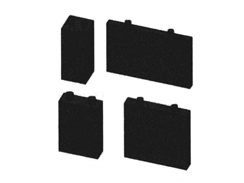
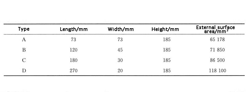
2. The influence of battery cell structure
The structure of the battery cell also has a very important influence on heat dissipation. For this factor, Zhang et al. constructed corresponding battery models for four 3.2V/50A·h square LiFePO4 power battery cells, as shown in Figure 2. The four types of batteries have the same volume and the same height, but different cross-sectional perimeters. The specific dimensions are shown in Table 1. They used a combination of experiments and numerical simulations to study the heat dissipation performance of the battery under different discharge rates and heat transfer coefficients, and obtained the optimal external dimensions and battery size through the optimization analysis of the experimental results. The size and surface heat transfer coefficient of the single battery have an important influence on the heat dissipation performance of the battery. When the external size of the 3.2V/50A·h square LiFePO4 power battery is 180mm×30mm×185mm, its heat dissipation performance is relatively best; when the size of the battery is 180mm×30mm×185mm, and the surface heat transfer coefficient is at least 20W·m-2·K-1, the maximum temperature of the single cell can be effectively controlled below the optimal operating temperature.