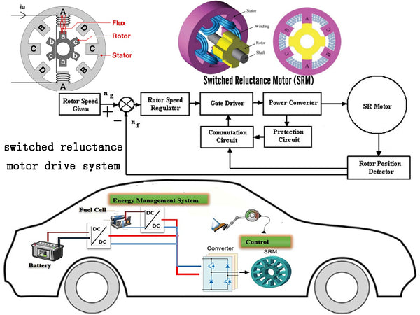
Switched reluctance motor is considered to be a very suitable motor drive system for electric vehicles because of its simple and reliable structure, low manufacturing cost, reliable converter and good torque-speed characteristics. The switched reluctance motor has no permanent magnets or windings on the rotor, which not only reduces the cost of the motor, but also allows for high-speed operation. The commonly used half-bridge inverter topology for switched reluctance motor drive systems is shown in Figure 1. The stator winding is connected in series with the upper and lower switches of each bridge arm of the inverter to prevent shoot-through short-circuit faults. The resulting problem is that each phase There are two heads, the length of the power line required and the difficulty of connection increase, which is different from the inverter for induction motor and permanent magnet synchronous motor drive. In addition, high efficiency over a wide range and simple control are significant advantages of switched reluctance motor drives.
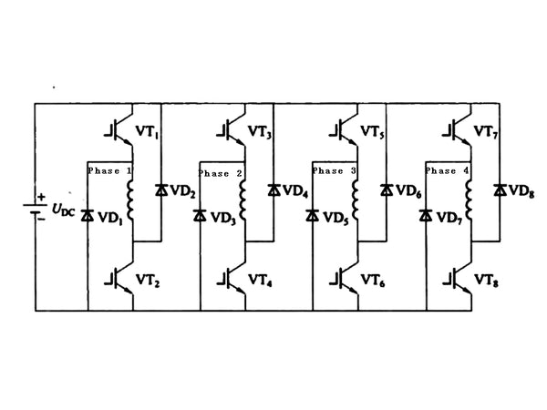
Figure 1 Commonly used half-bridge inverter topology for switched reluctance motor drives
Both the stator and the rotor of the switched reluctance motor are of salient pole structure, and there are concentrated windings on the stator. Due to this doubly salient structure and continuously changing inductance, highly saturated pole tips, and edge effects of poles and slots, finite element analysis is often used in the design of switched reluctance motors to determine motor parameters and performance. The stator and rotor can have many choices in structure, but in order to rotate continuously, the following conditions need to be met: the stator poles and rotor poles must be evenly distributed on the circumference, and the number of poles Ns and Nr of the stator and rotor must satisfy the following relationship
{Ns=2mq
{Nr=2(mq±1)
where q is the number of phases of the motor;
m—constant, equal to 1 or 2.
The larger the number of stator and rotor poles, the smaller the torque ripple. However, considering factors such as electric motor design, manufacturing and cost, the commonly used three-phase 6/4 structure and four-phase 8/6 structure are shown in Figure 2. In addition, it can be seen from the topology of the switched reluctance motor driver in Figure 1 that with the increase of the number of phases, the number of switching devices used in the driver increases accordingly, and the cost increases accordingly.
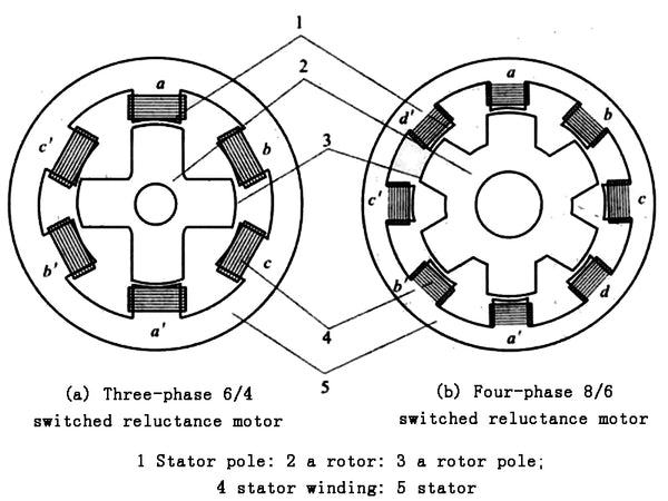
Figure 2 Structure sectional view of commonly used switched reluctance motor
The working principle of the switched reluctance motor is based on the principle of minimum reluctance. The torque is caused by the rotor tending to align the stator poles of the excitation. The analytical expression of the torque can be obtained by the partial derivative of the magnetic co-energy to the rotor position angle under a given current, that is,
T(θ,i)=1/2i²·dL(θ)/dθ
where θ——rotor position angle;
i——phase current;
L(θ)—Non-saturated phase inductance.
In the case of saturation, the torque cannot be calculated by a simple algebraic equation, but needs to be replaced by an integral equation, i.e.
T(θ,i)=∫i0[∂L(θ,i)]/∂θ·idi
T=3/2p[ψmIq-(Lq-Ld)IdIq]
{Ns=2mq
{Nr=2(mq±1)
It can be seen from the above two equations that the torque direction is independent of the polarity of the phase current, and the driving torque can only generate dL/dθ>0 in the direction of increasing inductance, otherwise negative torque will be generated. This means that position information is necessary for the control of switched reluctance motor drives. Switched reluctance motor output torque is the sum of all phase torques. Torque ripple occurs because each phase can only produce positive torque on half of the rotor pole pieces. Switched reluctance motors often generate vibration and noise due to the severe saturation between poles and the edge effect of poleslots.
The switched reluctance motor has a speed at which the back EMF is equal to the DC bus voltage, and this speed is called the base speed. The switched reluctance motor drive has two basic operating modes: when the motor base speed is lower than the phase current can be controlled by chopping, called current chopping control (CCC), in this mode it can effectively Control the output torque to achieve constant torque control; when running at high speed, the back EMF of the phase winding limits the peak value of the phase current. At this time, the on-off of the phase switch is controlled according to the rotor position, which is called angular position control (APC). In this mode the motor can run with constant power. The torque-speed characteristics of the switched reluctance motor are shown in Figure 3.
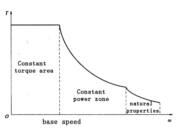
Figure 3 Torque-speed characteristic diagram of switched reluctance motor
Switched reluctance motor drives limit their widespread use in electric vehicles due to noise and torque ripple. In recent years, some studies have used a fuzzy sliding mode control method to drive the switched reluctance motor, and the fuzzy control technology is used to deal with the nonlinear problem of the motor: the sliding mode control is used to improve the smoothness of the control. In addition, the constant power operating region can be extended to 3-7 times the base speed by adjusting the phase lead excitation. Others use active vibration cancellation technology, which reduces noise by introducing a reverse vibration to cancel certain vibration patterns. The output of the switched reluctance motor is twice that of the induction motor and permanent magnet synchronous motor with the same number of phases, and the output of the controller is also increased accordingly, which will increase the length and difficulty of the phase power line in the application of electric vehicles.


