
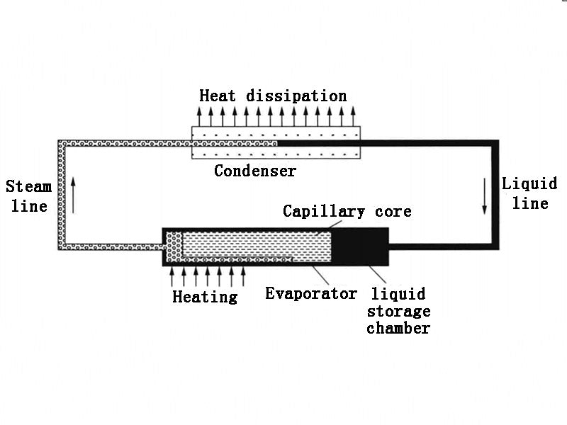
The loop heat pipe is an efficient phase change heat transfer device. The loop heat pipe was proposed by the Soviet scientist Maydanik in the 1980s. The loop heat pipe usually consists of an evaporator, a condenser, a liquid storage chamber, a steam pipeline and a liquid pipeline to form a loop system. The specific structure is shown in Figure 1. Among them, the evaporator is a very important part of the loop heat pipe, which is generally composed of a capillary wick, a steam channel, a liquid inlet pipe, a tube shell and a liquid accumulator. The loop heat pipe has the advantages of good anti-gravity performance, strong heat transfer ability, and convenient arrangement in the equipment. At the same time, the steam line and the liquid line of the loop heat pipe are separated from each other, and it also has the structural characteristics of an integrated evaporator and compensator. This determines that the resistance carried by the vapor and liquid is relatively small, the heat is transmitted in multiple directions and long distances, and the starting speed is relatively flexible.
At present, loop heat pipe evaporators usually have two structural forms, one is a cylindrical evaporator loop heat pipe, and the other is a flat plate evaporator loop heat pipe. The structural advantage of the cylindrical loop heat pipe is that when the heat source is in full contact with the evaporation part of the heat pipe, the evaporation part is heated evenly; in addition, the contact surface between the supercooled liquid and the capillary wick is large, and the capillary wick can be fully wetted. Compared to a conventional cylindrical loop heat pipe of the same size, the contact area between the flat-plate loop heat pipe and the heating device of the equipment is larger, so that the capillary core is heated more evenly, and the heat transfer ability of the loop heat pipe can be better exerted. The angle between the temperature gradient of the flat plate evaporator and the velocity gradient of the working fluid flow is small. From the perspective of field synergy, the flat plate loop heat pipe has more advantages than the traditional cylindrical loop heat pipe, especially in the field of high heat flux density electronic device heat dissipation, the flat loop heat pipe has greater potential. However, the loop type heat pipe also has several working limitations, namely capillary limitation, start-up limitation, liquid subcooling limitation and liquid storage chamber volume limitation, which restrict the development of the loop type heat pipe.
With the rapid development of society, people have higher and higher requirements for miniaturized electronic technology. At the same time, in order to better understand the efficient transfer of heat in micro and small spaces, the research on miniaturization is one of the inevitable trends of today's development. Figure 2 is a diagram of the internal structure of the micro-plate loop heat pipe. It can not only ensure good thermal conductivity and maintain temperature uniformity, but also reduce the volume and mass of the heat pipe itself to a large extent, so that the heat pipe can be better used in the heat dissipation system of small integrated electronic devices.

The working principle of the loop heat pipe is: due to the external heat load, the working fluid in the steam channel inside the evaporator is heated on the surface of the capillary wick to become steam and enter the steam pipeline, the steam becomes a liquid working substance due to the condensation of the tube wall and the condenser, thereby releasing latent heat, and the liquid working medium returns to the liquid storage chamber through the liquid line, effectively supplementing the liquid working medium consumed by heating and evaporation in the evaporator; the flow of the liquid working medium forms a similar meniscus on the outer surface of the capillary core, thereby forming a capillary force, and the working medium in the liquid storage chamber is sucked into the capillary core by the capillary force; the liquid working medium is again subjected to external heat load and turns into steam and enters the steam line. Through the above cycle process, the system continuously transfers heat from the heat source to the condenser, and then dissipates it to the heat sink.
China has carried out research on heat pipe battery cooling systems based on loop heat pipes. For flat loop heat pipes, it can be sandwiched between two batteries, while for cylindrical loop heat pipes, it can be placed between several batteries. In general, the evaporator of the loop heat pipe is attached to the heat source part of the battery board, and a thermally conductive material with high thermal conductivity is coated between the loop heat pipe evaporator and the battery board(such as silica gel, etc.) to minimize the contact thermal resistance between the battery and the heat pipe. When the heat load is large enough, the loop heat pipe starts to operate, and the loop heat pipe continuously brings the heat generated by the battery from the heating end to the cooling end, and then dissipates it to the heat sink. Park et al. designed an optimized loop-type heat pipe for cooling lithium-ion batteries on military aircraft. They used the finite difference method to analyze the heat transfer characteristics of the loop heat pipe in detail, but the main purpose is to analyze the heat dissipation capacity of the loop heat pipe and guide the design and optimization of the loop heat pipe. Through the experimental results, it is found that the loop type heat pipe can not only work well under the changing thermal load, keeping the temperature of the battery at about 10℃, but also through the results of the optimized design, it is found that under the same thermal conditions, the number of heat pipes used by Park is 12% less than that designed by Adoni, and the effect achieved is also ideal.


