

VFD (Variable Frequency Drive) and inverters are widely used in our daily life, but do you know how they work? Have you ever wondered the differences between VFD vs inverter?
This article will introduce the working principles, functions and characteristics of VFD and inverters respectively, and compare the differences between VFD vs inverter for your reference.
Main content:
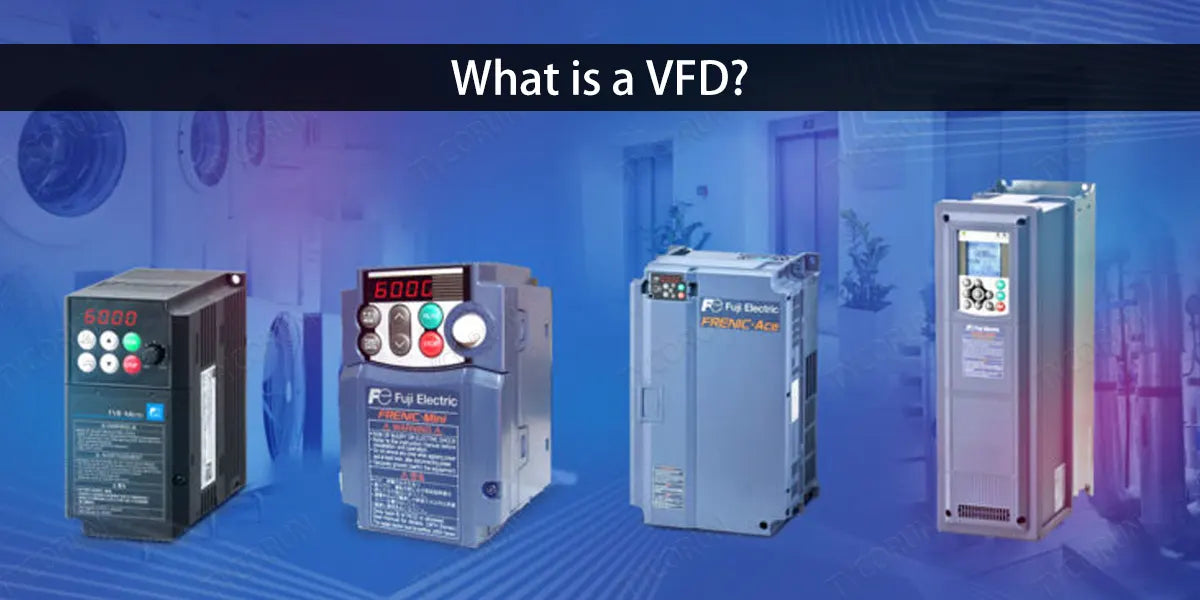
1. What is a VFD?
Before getting to compare VFD vs inverter, let’s first get to know what they are. Variable Frequency Drive (VFD) is a power control device that applies frequency conversion technology and microelectronics technology to control AC motors by changing the frequency of the motor's operating power supply. The frequency converter is mainly composed of rectifier (AC to DC), filtering, inverter (DC to AC), braking unit, drive unit, detection unit, microprocessing unit, etc.
When compare VFD vs inverter, the VFD relies on the switching of the internal IGBT to adjust the voltage and frequency of the output power supply, and provides the required power supply voltage according to the actual needs of the motor, thereby achieving the purpose of energy saving and speed regulation.
In addition, the VFD also has many protection functions, such as overcurrent, overvoltage, overload protection, etc. With the continuous improvement of industrial automation, VFDs have been widely used.
2. How VFD works
The VFD relies on the switching of the internal IGBT to adjust the voltage and frequency of the output power supply, and provides the required power supply voltage according to the actual needs of the motor, thereby achieving the purpose of energy saving and speed regulation.
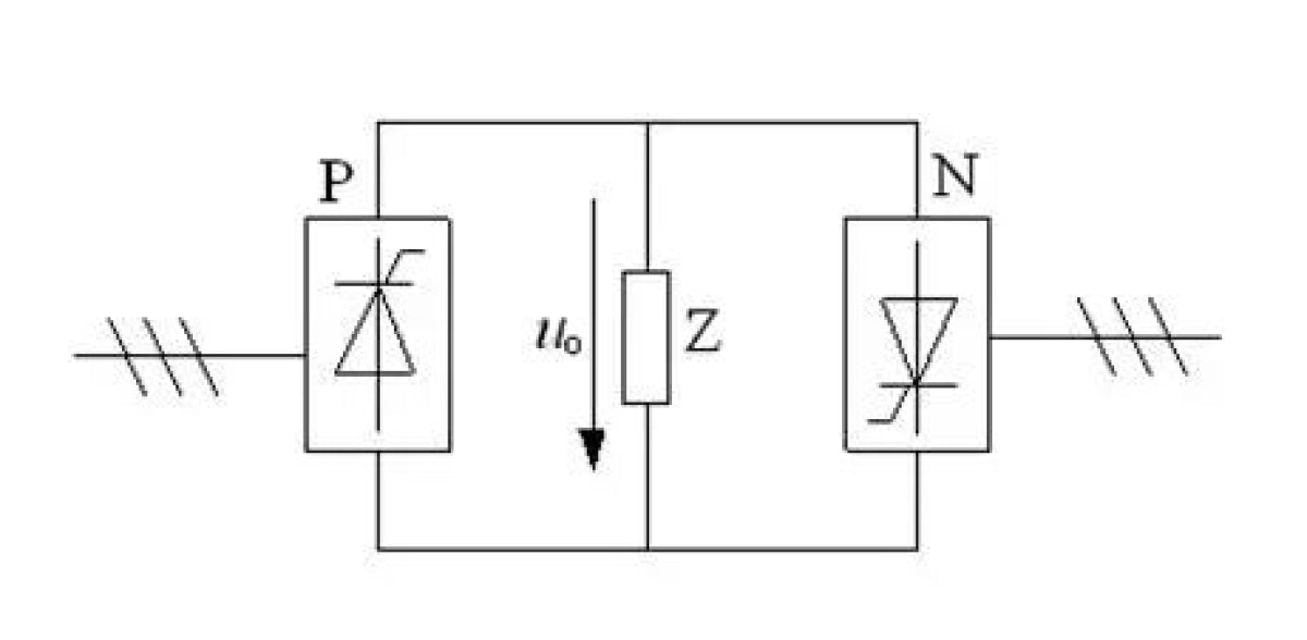
The picture below shows a circuit for changing the AC frequency. P and N are converter circuits. The AC power can be adjusted to DC power and loaded into the load Z. When the pulse signal given to P has a sinusoidal pattern, the set DC will have a sinusoidal pattern, and it is the upper half of the sinusoidal curve, and the period is the sinusoidal regular period of the pulse signal, which is an integer multiple of the AC cycle.
Through the cooperation of P and N, a periodic sinusoidal current is formed on the load Z, and the frequency can be adjusted according to the pulse signal period. This is the working principle of the VFD.
AC variable frequency power supply has certain requirements for environmental use. Factors such as ambient temperature, humidity, dust, acid and alkali, corrosive gases, etc. must be considered. The most effective energy-saving measure is to use a VFD to control the flow.
Due to technical specifications, many machines require motors that can control speed. In the past, DC control required speed control where AC motors were trying to control speed. However, the design of DC motors is complex, cumbersome, and difficult to maintain. Therefore, with the development of speed control technology, AC control gradually replaces DC control, and direct vector torque control is usually required to meet preparation requirements.
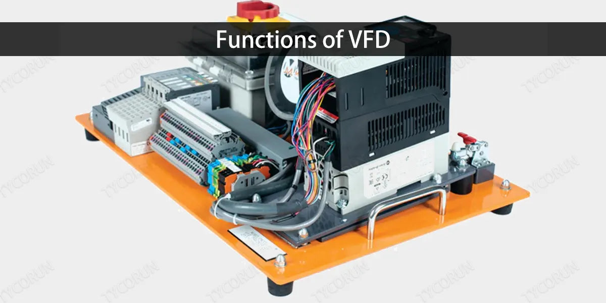
3. Functions of VFD
① Adjust the torque limit
After frequency control, the corresponding torque limit can be set to protect the machinery from damage, thereby ensuring the continuity of the process and the reliability of the product. The current frequency conversion technology makes not only the torque limit adjustable, but also the torque control accuracy reaching about 3% to 5%. Under the power frequency state, the motor can only be controlled by detecting the current value or thermal protection, but cannot set the precise torque value to operate like in variable frequency control.
② Control the stopping method
Just like controllable acceleration, in variable frequency speed regulation, the stopping method can be controlled, and there are different stopping methods to choose from (deceleration stop, free stop, deceleration stop + DC braking), which can also reduce the impact on mechanical components, thus making the entire system more reliable and the life span will be increased accordingly.
③ Energy saving
VFD energy saving is mainly manifested in the application of fans and pumps. In order to ensure the reliability of production, a variety of production machinery in the design of the power drive, have left a certain amount of surplus. When the motor can not run under full load, in addition to meet the power drive requirements, the excess torque increases the consumption of active power, resulting in a waste of electrical energy.
For fans, pumps and other equipment, the traditional speed control method is to adjust the inlet or outlet of the baffle, valve opening to adjust the amount of air and water supply, its input power, and a large amount of energy consumption in the baffle, valve interception process. When using frequency conversion speed control, if the flow requirements are reduced, by reducing the speed of the pump or fan can meet the requirements.
④ Reversible operation control
Comparing VFD vs inverter, in the VFD control, to achieve reversible operation control without additional reversible control devices, we only need to change the phase sequence of the output voltage can be, so as to reduce maintenance costs and save installation space.
⑤ Reduce the mechanical transmission components
Since the current vector control frequency converter plus synchronous motor can achieve efficient torque output, thereby saving mechanical transmission components such as gearboxes, ultimately forming a direct frequency conversion transmission system. It will reduce the cost and space and improves stability.
4. What is an inverter?
When compare VFD vs inverter, an inverter is a current converter that converts 12V or 24V DC into 240V, 50Hz or other types of AC. The output current can be used in mobile power areas or various devices to meet the needs of users without power sources. For further information, you can also check 12v vs 24v inverter.
The inverter converts DC power (from off grid storage batteries) into AC power (generally 220V, 50Hz wave). It consists of inverter bridge, control logic and filter circuit. Inverters are widely used in air conditioners, home theaters, electric grinding wheels, power tools, sewing machines, DVDs, VCDs, computers, TVs, washing machines, range hoods, refrigerators, video recorders, massagers, fans, lighting, etc.
With an inverter, DC power (LFP battery, circuit breaker, fuel cell) can be converted into AC, so that electrical equipment such as laptops, mobile phones, and digital cameras can be reliably protected. Inverters are increasingly in demand for wind and solar power generation. Small inverters from 500w inverter to 3000w inverter can also provide AC power in the field for use in cars, boats, and portable appliances.
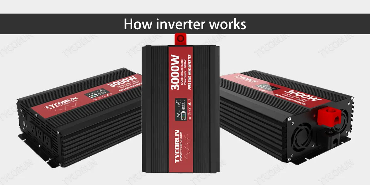
5. How inverter works
When compare VFD vs inverter, unlike VFD who relies on the switching of the internal IGBT to adjust the voltage and frequency of the output power supply, the working principle of the inverter is mainly to convert alternating current into direct current, and then use electronic components to switch the direct current into alternating current. Comparing VFD vs inverter, the working process of inverter is generally divided into four major processes: rectifier circuit, smoothing circuit, control circuit, and inverter circuit.
① Rectifier circuit
The function of the rectifier circuit is to convert AC power into DC power. The rectifier circuit is generally a separate rectifier module.
② Smoothing circuit
The smoothing circuit contains a pulsating voltage 6 times the frequency of the power supply in the rectifier and the rectified DC voltage. In addition, the pulsating current generated by the inverter also changes the DC voltage. In order to suppress the voltage fluctuation, inductors and capacitors are used to absorb the pulsating voltage. Generally, the DC part of the general VFD power supply has margin for the main circuit, so the inductor is omitted and a simple capacitor filter smoothing circuit is used.
③ Control circuit
Nowadays, variable frequency speed regulators basically use 16-bit or 32-bit microcontrollers or DSP as the control core to achieve full digital control.
④ Inverter circuit
The inverter circuit is the opposite of the rectifier circuit. The inverter circuit converts the DC voltage into an AC voltage of the desired frequency, and turns on and off the power switching devices of the upper and lower bridges at a determined time. As a result, three-phase AC voltages with a phase difference of 120° electrical angle from each other can be obtained on the three phases of the output terminals U, V, and W.
6. Features of inverter
- High conversion efficiency and fast startup;
- Good safety performance: the product has 5 protection functions - short circuit, overload, over/under voltage, and over temperature;
- Good physical properties: the product adopts an all-aluminum shell with good heat dissipation performance, hard oxidation treatment on the surface, good friction resistance, and can resist extrusion or impact from certain external forces;
- Strong load adaptability and stability.
7. Differences between VFD vs inverter
Above we have introduced the functions and working principles of VFD and inverter, now let’s compare VFD vs inverter.
Comparing VFD vs inverter, the VFD integrates high-voltage and high-power transistor technology and electronic control technology to become an independent transmission component. The function of the VFD is to change the frequency and amplitude of the AC motor's power supply, thereby changing the period of its moving magnetic field to achieve the purpose of controlling the motor's speed.
The inverter not only needs to invert the DC power supply into AC power supply, but also needs to continuously rectify the AC power supply into DC power supply. Comparing VFD vs inverter, the inverter converts DC power into AC power. In short, the inverter can be regarded as the output part of the VFD.
① Inverter is a component used to convert DC power into AC power; VFD is a component used to change the frequency of AC power when compare VFD vs inverter.
② The inverter converts DC power into AC power, and the frequency can also be adjusted; the VFD converts the input AC power into an AC power output of the required frequency; its principle is as follows "AC-DC-AC" or "AC-AC", among which "AC-DC-AC" is more common.
③ The inverter must have a frequency adjustment part, while the inverter only needs a fixed output frequency when compare VFD vs inverter.
Related posts: inverter vs generator for RV, AC coupling vs DC coupling, pure sine wave vs modified sine wave inverter


