


Short circuit faults are more common than other fault types. Short circuit faults in different equipment have some similarities and also some different characteristics. Today we will mainly talk about the short circuit characteristics of solar inverters.
The power supply in the power system traditionally refers to the synchronous generator incorporated into the power system. However, with the development of distributed power generation technology, various forms of power generation devices have been integrated into the power system. According to the way distributed power sources are connected to the grid, power sources can be roughly divided into the following three categories:
- The power supply that is connected in parallel to the grid through rotating electrical machines and converters mainly refers to doubly-fed wind power generation systems;
- Power sources that are connected to the grid only through converters mainly include direct-drive wind power generation systems, solar power backup systems for homes, LFP battery, micro gas turbines, etc.;
- Power sources that are connected to the grid only through rotating motors are mainly small synchronous generators, and the most common ones are fast-response diesel generator sets.
Main content:
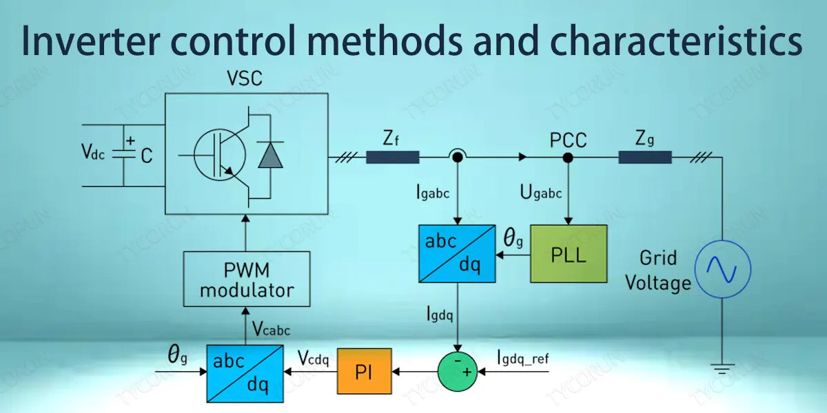
1. Inverter control methods and characteristics
The typical topology of a solar inverter is as follows:
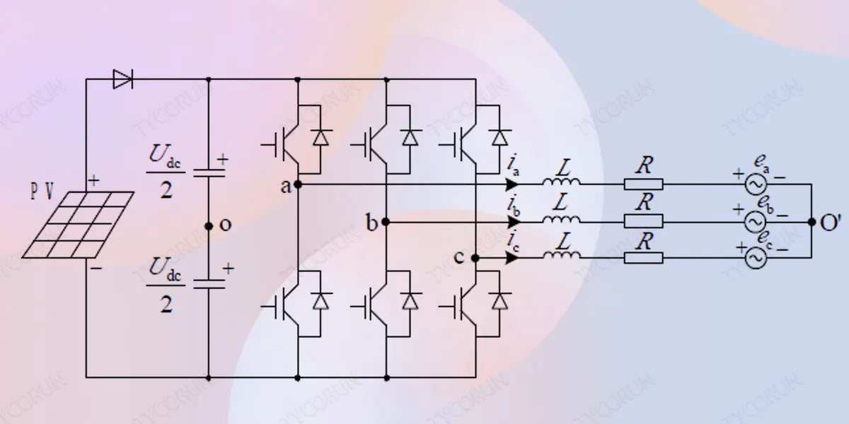
The main control methods of solar inverters include: PI control, hysteresis control, double closed-loop control, space vector PWM control, deadbeat control, repetitive control, proportional resonance control, etc. And among grid-connected solar inverters, the current-mode control method is more mature and widely used, and it generally adopts double closed-loop control.
In the double closed-loop control, the inverter voltage regulator acts as an outer-loop control, controlling the output voltage Udc of the DC side of the inverter to track the given value of voltage Udcref on the one hand; on the other hand, it obtains the reference value id of the active input current component and the reference value iq of the reactive current component through the PI regulator. The role of the current inner-loop is to carry out the current control in accordance with the current commands of the output of the outer-loop of the voltage.
The short-circuit fault characteristics of the PV system mainly depend on the characteristics of its control mode. In order to ensure that the short-circuit current does not exceed the limit value of the inverter when a short-circuit occurs in the power system, a saturation module is generally added to the current inner loop in the control loop.
When a fault occurs, the reference current of the inner loop will be limited, and by setting the upper limit of the saturation module, the fault current will be limited to the permissible range, and the short-circuit current will be limited to 1.2~1.5 times of the rated current. When the saturation module fails, the outer loop control of the dual-loop control system will fail and the system becomes pure current control.
2. What happens to the inverter when a short circuit occurs?
When a short circuit occurs in the system, there are two situations of the inverter output:
① The saturation module does not activate
When a remote fault occurs, the system's power outer loop control plays a decisive role. The active current increases, and the increased current amplitude is within the limiting threshold. Therefore, the fault characteristics at this time are consistent with the response to a sudden increase in load.
After a short transition process, the system reaches a new steady state. At this time, the output power is still equal to the output power before the fault occurred, and the system is equivalent to a constant power source.

② The saturation module activates
When a near-end fault occurs, due to the decrease in port voltage, if calculated according to the equal power source, a larger current will be output in order to keep the power unchanged; if the output current exceeds the limit of the inverter, the voltage outer loop will lose its function and the double loop control will become pure current control.
Since the current saturation control module can reach the steady-state value in a short time, the grid disturbance voltage disappears after entering the steady state, and the output current value of the photovoltaic system is equal to the set value of the current saturation module.
In the two cases above, there will be a short transition process after the fault occurs. A certain amount of harmonics may be generated during this process. The length of the process mainly depends on factors such as the size of the DC side capacitance of the system and the parameters of the outer loop control in the dual-loop control, DC side input power, etc.
3. Characteristics of the inverter when different faults occur
Let's take a look at the inverter output characteristics when there are three-phase faults on the high-voltage side of the step-up transformer, three-phase faults on the low-voltage side of the step-up transformer, phase-to-phase faults and single-phase faults. Before the fault, the inverter output positive sequence current was 276A, and there was no zero sequence and negative sequence current.
① Three-phase fault on the high voltage side of the booster transformer
When this fault occurs, the low-voltage side current and voltage waveforms are as shown below:
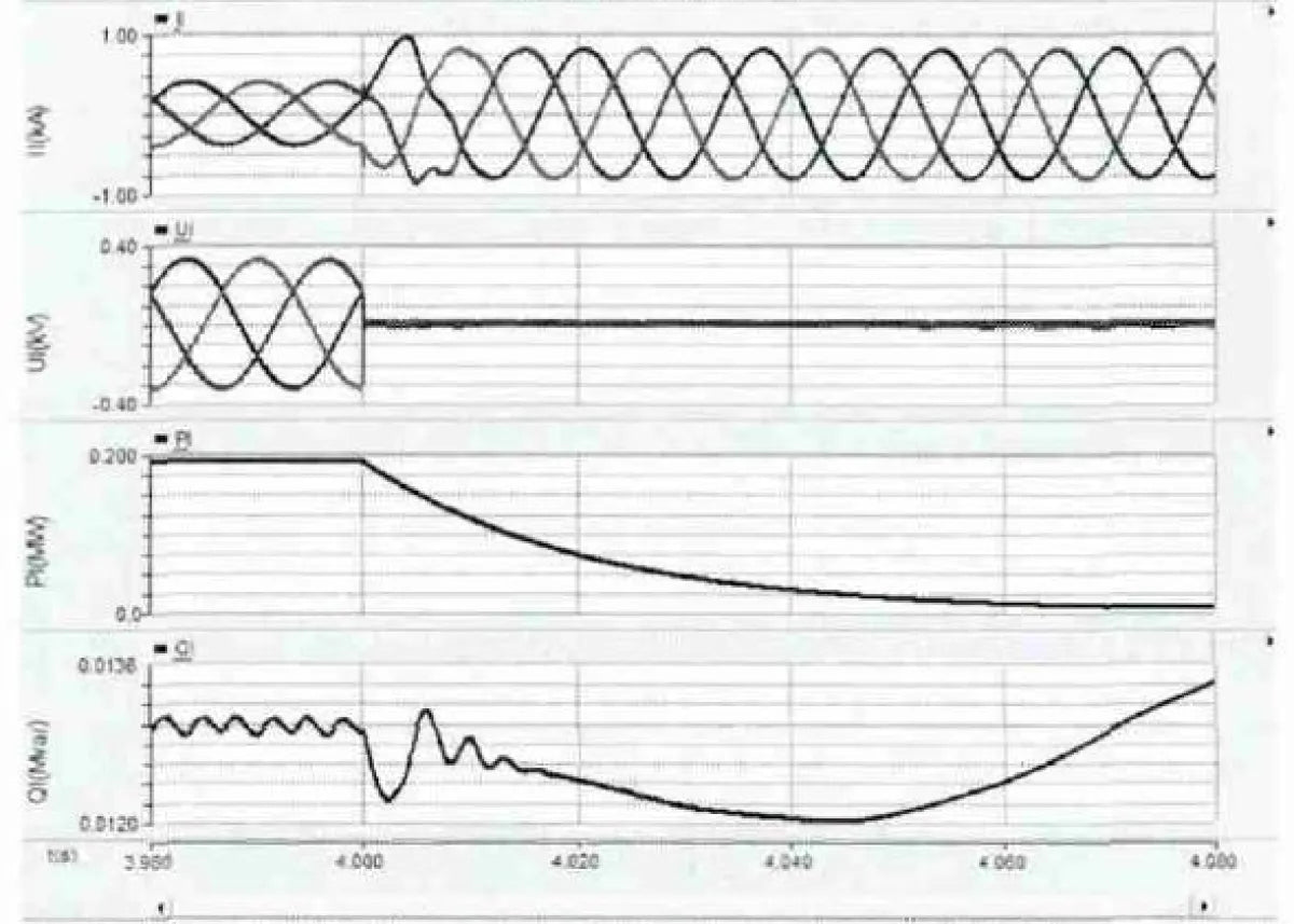
There is a 10ms transition process during the fault. After the process is over, the current and voltage tend to be stable. After the inverter is stabilized, the positive sequence current output is 544A, and the power direction is positive.
② Three-phase fault on the low-voltage side of the boost transformer
When this fault occurs, the low-voltage side current and voltage waveforms are as shown below:
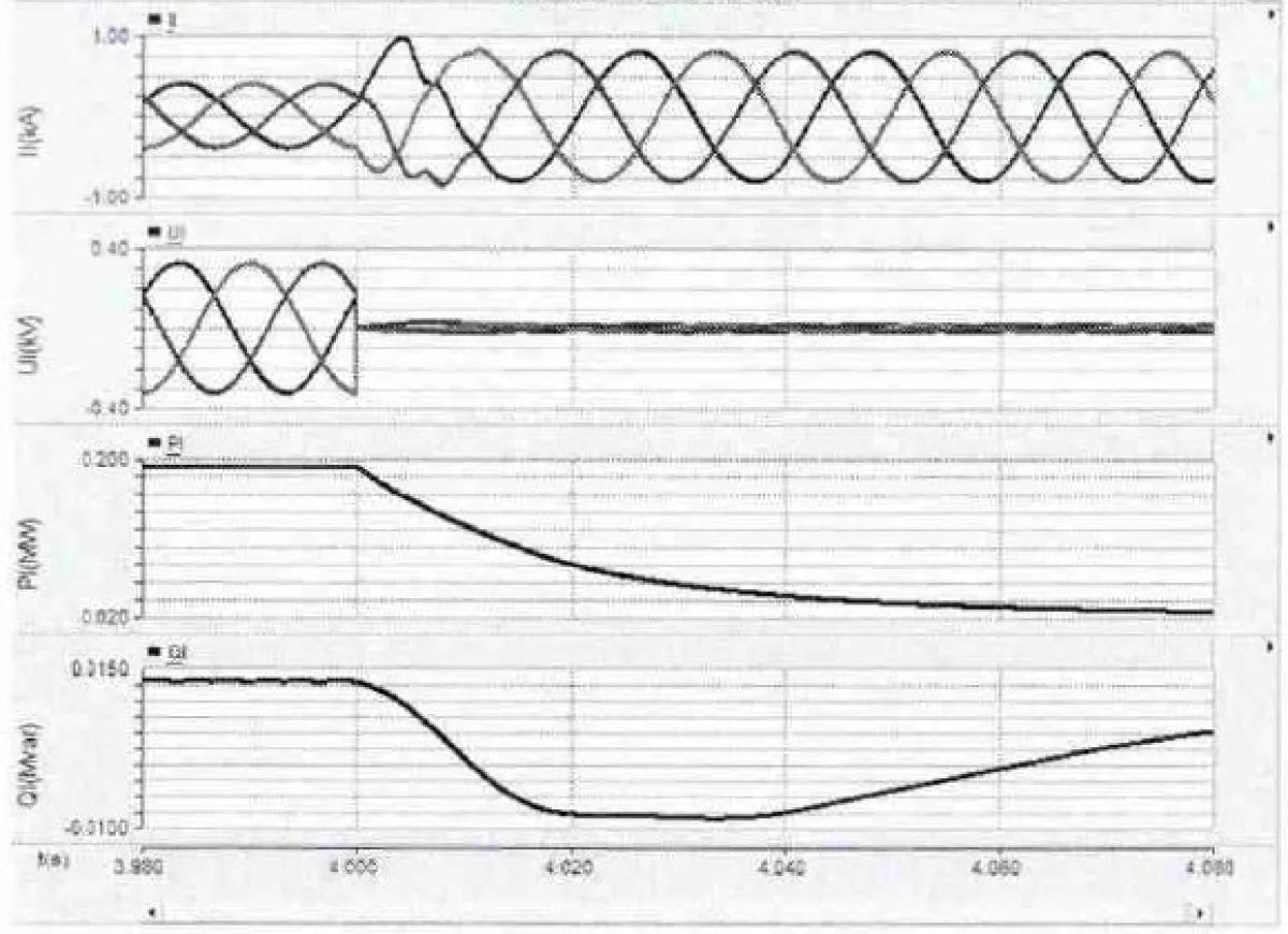
There is also a 10ms transition process. After the process is over, the current and voltage tend to be stable. After the inverter is stabilized, the positive sequence current output is 549A, and the power direction is positive. The fault current is basically the same as the three-phase fault on the high voltage side of the step-up transformer.
③ Fault between two phases on the low voltage side of the boost transformer
When this fault occurs, the low-voltage side current and voltage waveforms are as shown below:
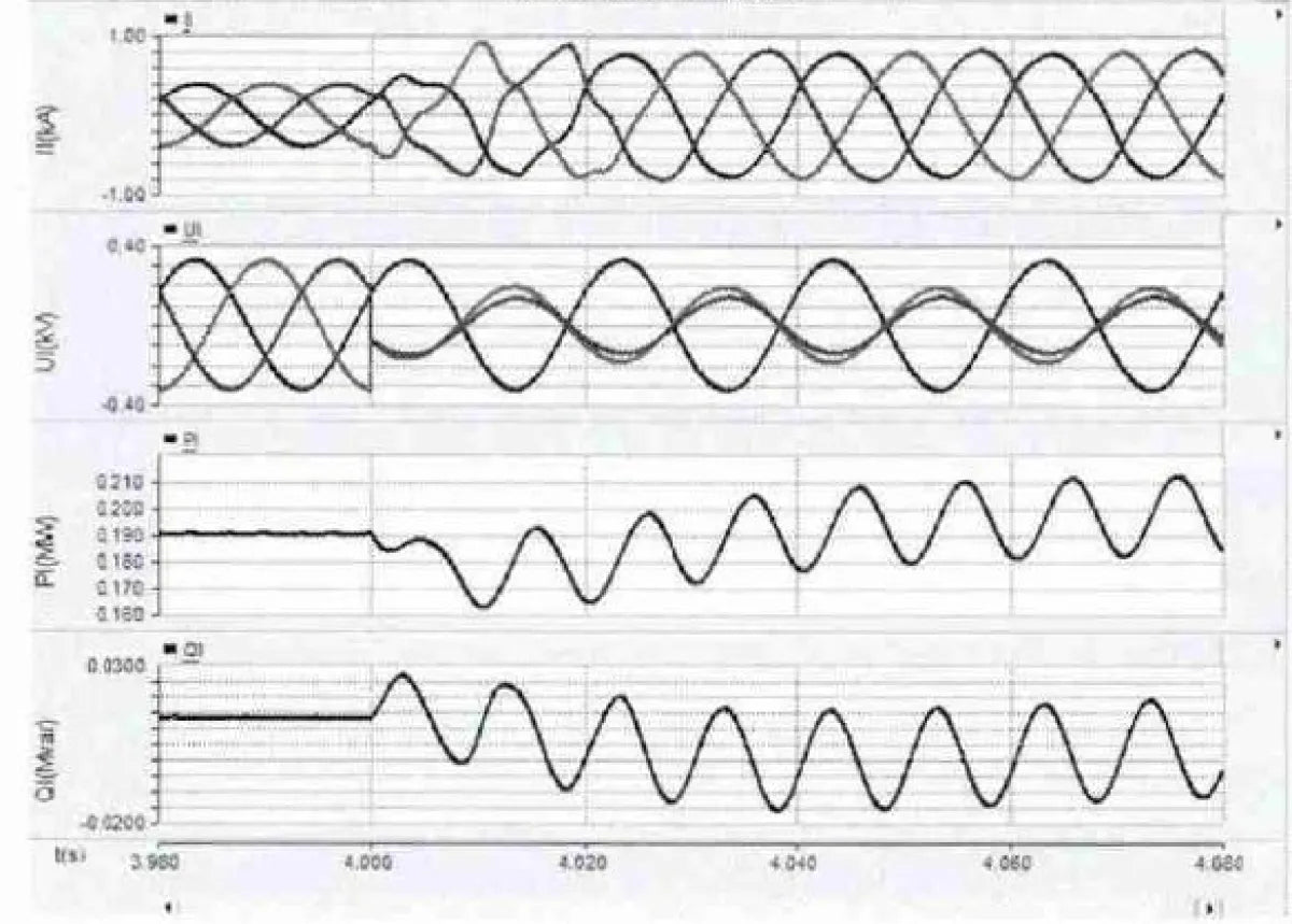
During the 10ms transition process, the fundamental wave amplitude is unstable during this period. After the transition, the fundamental wave amplitudes of the current and voltage tend to be stable; the positive sequence current output by the inverter after stabilization is 560A, and the power direction is positive.
The amplitudes of the non-fault phase current and the fault phase current are basically the same, and there are no zero sequence and negative sequence components after stabilization.
④ Single-phase fault on low voltage side
When this fault occurs, the low-voltage side current and voltage waveforms are as shown below:
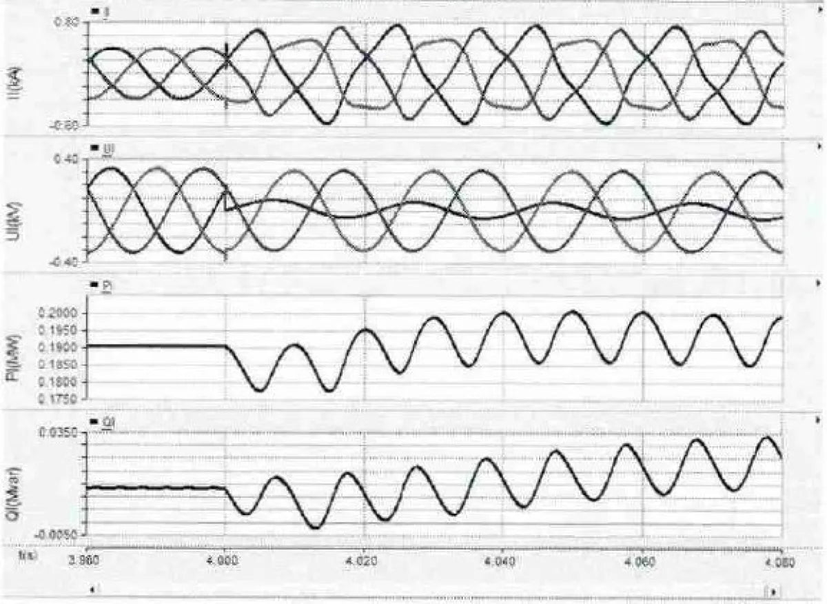
The amplitude of the current fundamental wave is unstable for 20ms during the fault process, and then basically stable; after 100ms of the fault, the positive sequence current stably output by the inverter is 445A, the power direction is positive, and the fault current is slightly smaller than the current when the three-phase fault occurs on the high-voltage side of the step-up transformer.
The amplitudes of the non-fault phase current and the fault phase current are basically the same, and there are no zero sequence and negative sequence components after stabilization.
4. Conclusion
To sum up, the main short circuit characteristics of solar inverters are:
- No matter what type of fault, the output power direction of the inverter can correctly reflect the fault characteristics;
- There is a short transition process during the fault process, and there is a certain harmonic component in this process;
- The time and peak value during the transition process are affected by many factors, including DC side capacitance, power outer loop parameters, input power, etc.;
- In the case of symmetrical and asymmetrical faults in the power grid, the inverter only outputs positive sequence current, without zero sequence and negative sequence current. During the fault process, whether it is a single-phase fault, a two-phase fault, or a three-phase fault, the three-phase currents have little difference, and the fault phase cannot be selected through the current;
- Due to the influence of the limiting effect in the inverter, the distance of the fault cannot be distinguished by the size of the current.
Related posts: top 10 solar inverters in Australia, what is PWM, inverter waveform


