

Main content:
1.General requirements for gas humidification systems
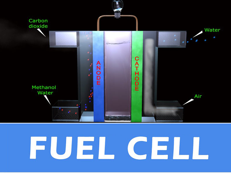
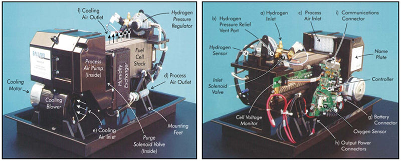
In this paper, the gas humidification system of PEFC fuel cell is studied. The electrolyte of the fuel cell is solid and made of polymer membrane. For this electrolyte, it is necessary to ensure adequate hydration of the membrane for good ion transfer performance. The ionic conductivity of dry polymer membranes is very low, but upon hydration, the conductivity increases rapidly (Nafion membranes can absorb almost 20% of their weight in water). In addition, when there is a water film around the membrane (each proton is surrounded by 2 to 5 water molecules), the protons can migrate under the action of the electric field force (and then form an electric current). However, the water balance of the membrane must be maintained because if the water is not properly controlled, the electrolyte membrane runs the risk of flooding or dehydration. If the membrane is flooded, the path of the reactant gas to the catalyst interface will be blocked, and if there is a current demand at this time, the voltage outside the cell will drop rapidly and greatly. If the membrane is dehydrated, the proton conductivity of the electrolyte membrane will drop, and it will not even be able to migrate. If the current demand at this time remains the same, it will cause the membrane resistance to increase and the voltage outside the battery to decrease accordingly. One of the main functions of the gas humidification system of the battery is to prevent the occurrence of membrane flooding or dehydration by measuring the voltage (either the stack voltage or the cell voltage). If the gas humidification system detects that the voltage is too low, it should stop operation to avoid further deterioration of the gas humidification system. The water circulation of the gas humidification system inside the PEFC fuel cell is shown in the figure below.
So, how does the risk of membrane flooding or membrane dehydration in gas humidification systems arise? This should be the result of the joint influence of various factors directly related to the internal physical and chemical evolution process of the battery and the operation process of the battery gas humidification system.
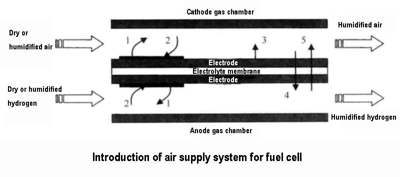
1) The cathode electrochemical reaction generates water, and the amount of water is related to the current output by the fuel cell.
2) During the migration of protons from the anode to the cathode, water is also transferred to the cathode, a phenomenon called "electroosmosis".
3) Due to the difference in water concentration between the two gas chambers, water diffuses from the cathode to the anode.
4) In order to prevent membrane dehydration, especially in high temperature operation, water is generally added to the reaction gas (cathode, anode, or both sides), but this will cause the water balance to shift.
5) The operating temperature of the battery and the temperature of the reaction gas at the battery inlet will also cause a shift in the water balance, and there will also be local water evaporation or condensation inside the battery, depending on its temperature and pressure conditions.
2.Humidification method of gas humidification system
In an autonomously operating polymer membrane battery gas humidification system greater than 1kW, the gas humidification system device is the second main component in its gas supply path. Likewise, its energy consumption ranks second. For the air supply system, there are several structural forms available: the passive gas humidification system scheme does not consume battery power and provides fewer parameters for the optimal operation of the gas humidification system; the active gas humidification system scheme is more effective, but consumes less energy Also high. We classify several scenarios as follows:
1) Self-humidification scheme using reacted raw water. For systems of more than a few hundred watts, it is dangerous to rely only on the raw water in the battery to maintain sufficient humidity in the electrolyte membrane unless there is a device to recycle the water. In fact, this is true. Even if the endogenous water is sufficient, some water will still escape from the battery, resulting in insufficient water.
2) Fuel humidification scheme. In most applications, an external gas humidification system device is used to humidify the gas entering the battery to provide moisture to the battery. Since the water produced by the reaction is generated at the cathode, the anode area is likely to be short of water first, and the membrane in the corresponding area is also prone to dehydration, which is why the fuel needs to be humidified. Most importantly, in order to control the risk of hydrogen leakage, the hydrogen supply path must be simplified and the number of components used should be minimized. If there is too much water, the electrolyte membrane will no longer absorb water, and the excess water must be discharged through the anode loop, but in order to reduce the consumption of hydrogen, the anode loop is rarely opened, and mostly in closed or internal circulation mode. Therefore, the anode drainage of the gas humidification system is more complicated.
3) "Oxidant humidification" scheme. This is the most commonly used solution. It utilizes the water concentration gradient between the cathode and the anode to promote the diffusion of water through the electrolyte membrane, thereby replenishing the lack of water in the anode, so that the two sides of the electrode can reach the water balance again.
4) Two-reactant humidification scheme. This solution is bulky, high cost, complex system, and has no certainty to improve the performance of the gas humidification system, so it is rarely used.
Depending on whether direct water exchange or water reserve buffers are used, we can divide gas humidification systems into two categories. Membrane exchangers and enthalpy wheels belong to the first type of gas humidification system, and the battery raw water is assumed to be self-sufficient for use; and the systems that require water injection and have a library separator belong to the second type of gas humidification system.
3.Membrane exchanger and enthalpy wheel for gas humidification system
The principle of this type of gas humidification system is to transfer the moisture in the oxidant downstream of the battery to the dry oxidant entering the battery, because the oxidant downstream of the battery is low in oxygen but rich in water vapor. These devices are made of porous membranes and operate completely passively: a humid air flow passes through one side of the membrane, a dry air flow passes through the other side of the membrane, and the membrane transfers moisture from the humid air to the dry air through a water concentration gradient. The NexaTM 1.2kWautonomous operation power module adopts this gas humidification system solution.
The enthalpy wheel consists of a rotating part made of a porous cylinder coated with a desiccant, which rotates slowly inside the mould and through which it improves water exchange. The hot and humid airflow from the battery penetrates into the wheel, and due to the dry coating on the surface of the porous cylinder, it can absorb the moisture in the exhaust gas and transfer it to the dry air stream entering the battery, while other components are evacuated. Some models give control of the rotational speed of the enthalpy wheel, providing a control variable for the amount of water exchange.
This device simplifies the system structure and reduces the number of parts compared to systems that require a water container. They do not require a condenser, consume little energy, and recover part of the enthalpy from the exhaust. However, they cannot control intake dew point or temperature. These parameters depend on the exhaust gas temperature and humidity, the operating point of the battery. When the battery is operating at its normal operating point, the load changes very slowly or quickly without causing problems. Conversely, if the output current of the gas humidification system is fixed at certain levels, or if the demand for moderate frequency current changes is the same as the water diffusion time constant of the porous material used, instability in the control of the gas humidification system can be induced.
4.Gas humidification system with water storage container
A gas humidification system with a water storage device can control the dew point of the intake air of the battery according to the temperature and the current corresponding to the amount of water generated, regardless of the operating point of the battery. This gas humidification system can be divided into two ways: water injection and distillation.
In the gas humidification system using the water injection method, the air to be humidified enters from the bottom of the cylindrical container, the water vapor is injected from the top, and the air is humidified in the process of rising in the container. The use of metal rollers in the cylindrical vessel facilitates the exchange of water vapour. Water injection can be calculated based on temperature, pressure, airflow and expected degree of humidification. A baffle at the bottom is used to recycle the water that is not carried away. The temperature of the injected vapor is a parameter that can be controlled for the gas humidification system, but the degree of humidification of the intake air of the battery is difficult to know precisely. In practice, if water appears on the partition, it means that some of the water has not been transferred, and the difference between the actual humidity and its set value is difficult to measure.
In another gas humidification system employing distillation, the temperature and humidity of the gas are allowed to be set independently and simultaneously and the transition time is shortened. The drying air flow is regulated by the delivery regulator, which is delivered to the distiller where saturated water vapor is formed at the temperature of the distiller, which is the maximum temperature of the entire circuit. The saturated water vapour of the intake air is then cooled in the exchanger, in this way the dew point temperature of the intake air is calibrated. The liquid water is evacuated to the separator, and the battery population temperature is finally corrected by the regenerator. This gas humidification system is regulated by two easily measurable parameters namely condenser outlet temperature and regenerator outlet temperature. In fact, the advantage of controlling only these two temperatures is the control reliability and rapidity that have been sought, and this solution completely controls the operating parameters of the gas humidification system and its repeatability. However, gas humidification systems need to hold large amounts of water at specific temperatures, and they are bulky and energy-intensive due to the many components. Therefore, it is currently only used in laboratory tests.


