

In electronic circuits, MOSFET diode is often applied and as switching elements. The full name of MOSFET diode is metal-oxide semiconductor field-effect transistor. Unlike other active devices, the special thing about power MOSFET is that it contains an inherent parasitic device - a MOSFET diode inside.
So what does a MOSFET diode do? What impact does MOSFET diode have on the inverter? This article will provide you with a comprehensive introduction.
Main content:
1. What is MOSFET diode
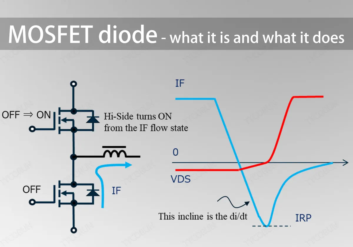
MOSFET diode is used in MOSFETs to protect the device from reverse EMF spikes caused by connected inductive loads. When the inductive load is connected to the drain of the MOSFET, the electric energy is immediately stored inside the load, and at the next moment when it is turned off, the stored EMF flows from the source of the MOSFET to the drain, causing permanent damage to the MOSFET.
There is an internal MOSFET diode between the drain and source of the device, which prevents the MOSFET from being damaged and protects the MOSFET by allowing back electromotive force spikes to pass through the MOSFET diode.
2. Basic functions of diodes
Diodes are very commonly used basic components. Before understanding the functions of MOSFET diode, let's first take a look at the basic functions of diodes, including anti-reverse connection, rectification, voltage stabilization, freewheeling, detection, voltage doubling, clamping, and envelope detection, etc.
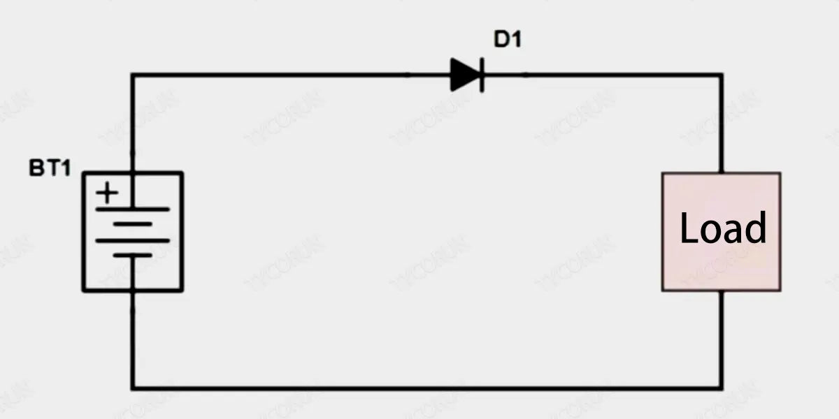
① Anti-reverse connection
In the main circuit, a diode is connected in series to realize the simplest and most reliable low-cost anti-reverse connection circuit by using the diode's unidirectional conduction characteristics. This low-cost solution is generally used in small current situations, such as small toys. Because there is usually a conduction voltage drop of 0.7V (silicon tube) when the diode conducts, if the actual current is very large, there will be a heat loss, which will cause heating.
Moreover, if the reverse connection voltage is very large and exceeds the reverse cut-off voltage, it will also break down the diode itself, causing the diode to fail and fail to prevent reverse connection, thus failing to protect the subsequent circuit.
② Rectification
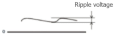
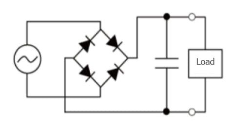
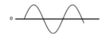
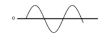
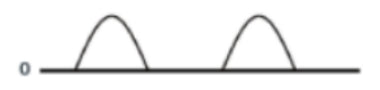
The function of the rectifier circuit is to convert the lower voltage AC output by the AC step-down circuit into unidirectional pulsating DC. This is the rectification process of AC. The rectifier circuit is mainly composed of rectifier diodes.
The voltage after passing through the rectifier circuit is no longer an AC voltage, but a mixed voltage containing DC voltage and AC voltage, which is customarily called unidirectional pulsating DC voltage.
|
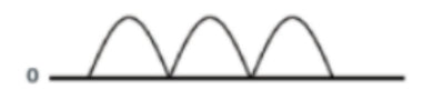
Full wave rectification |
Half wave rectification |
|
|
Circuit configuration |
|
|
|
Input voltage waveform |
|
|
|
Rectified voltage waveform |
|
|
|
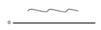
Rectified and smoothed voltage waveform |
|
 |
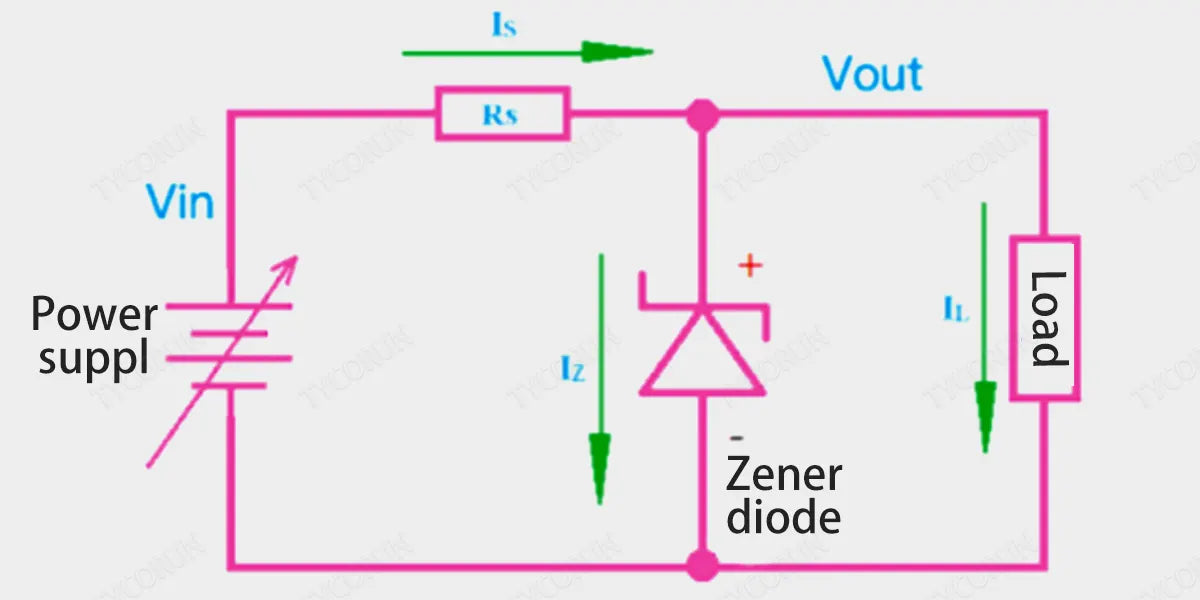
③ Voltage stabilization
The diode with voltage stabilizing function is called Zener diode. Utilizing the reverse breakdown state of the PN junction, its current can change within a wide range while the voltage remains basically unchanged. Its basic circuit structure is shown in the figure below.
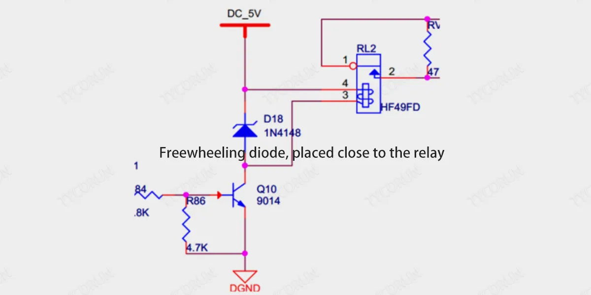
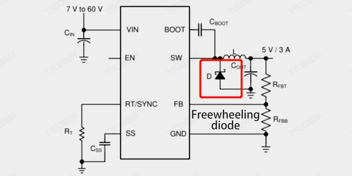
④ Freewheeling
Freewheel diodes are connected in parallel at both ends of the coil (inductive component). When the coil passes current, it will generate an induced electromotive force at both ends. When the current disappears, its induced electromotive force will produce a reverse voltage on the original components in the circuit.
When the reverse voltage is higher than the reverse breakdown voltage of the original component, the original component such as a transistor will be damaged. Freewheel diodes are connected in parallel at both ends of the line.
When the current flowing through the coil disappears, the induced electromotive force generated by the coil is consumed through the loop formed by the diode and coil, thus protecting the safety of other components in the circuit.
Or the freewheeling diode in the BUCK chip circuit.
⑤ Detection
The peak detection circuit detects the maximum value of the input signal amplitude. Its working principle is: when the input voltage amplitude is greater than the forward voltage of the diode, the diode is turned on, the output voltage is added to the capacitor C1, and both ends of the capacitor are charged.
When the input voltage amplitude is lower than the previous input voltage amplitude, the diode is in the reverse biased cut-off state. At this time, the voltage across the capacitor remains basically unchanged; if a signal is input again, the input voltage amplitude must be higher than the voltage across the capacitor at this time (that is, the forward voltage applied to the diode), so that the diode can conduct.

⑥ Voltage Doubling
The voltage doubler rectifier circuit uses the guiding function of the diode to charge and discharge the capacitor. When the voltages of several capacitors are superimposed on each other, a higher voltage output can be obtained. Therefore, the voltage doubler rectifier circuit is often used in circuits to increase the voltage.
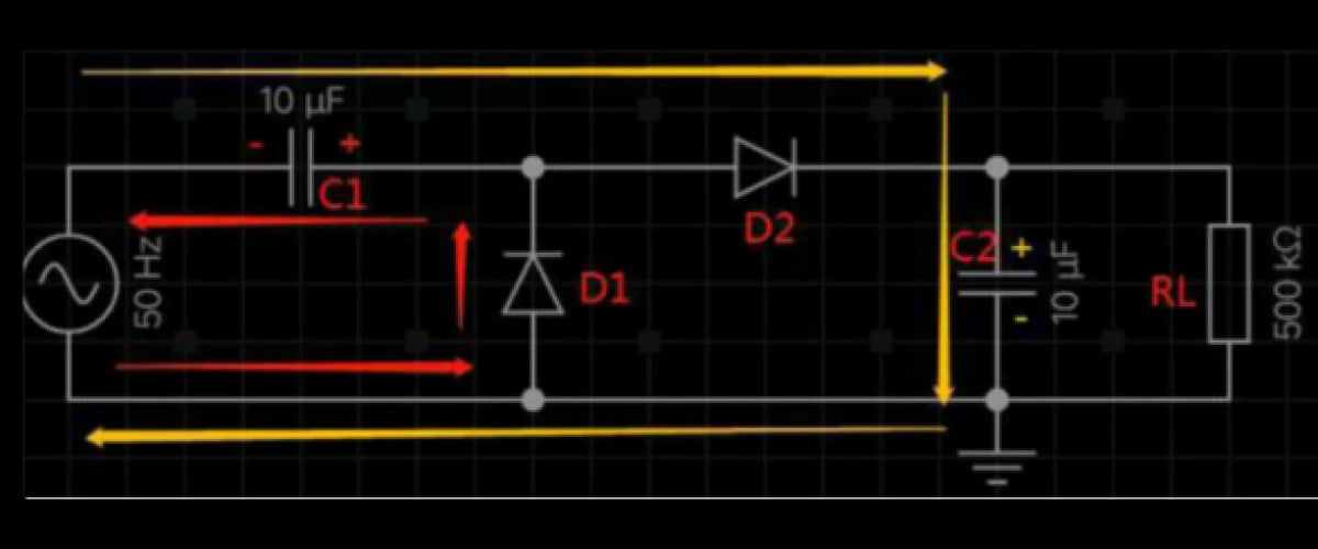
The picture below is a schematic diagram of a 2x voltage circuit. Its working process is roughly analyzed as follows:
During the negative half cycle of the power supply, diode D1 is turned on and D2 is turned off. The current flows out from the lower end of the power supply through D1 and C1 and returns to the power supply. Therefore, the right side of the capacitor C1 is positive and the left side is negative, as shown by the red arrow in the figure below.
During the positive half cycle of the power supply, the voltage on the capacitor C1 is superimposed on the power supply voltage, causing the diode D2 to conduct, and the diode D1 to cut off. The capacitor C2 is up and down, and the peak voltage can reach twice the peak voltage of the power supply, that is, voltage doubling is achieved.
The current direction during this half cycle is shown by the orange arrow in the figure below:
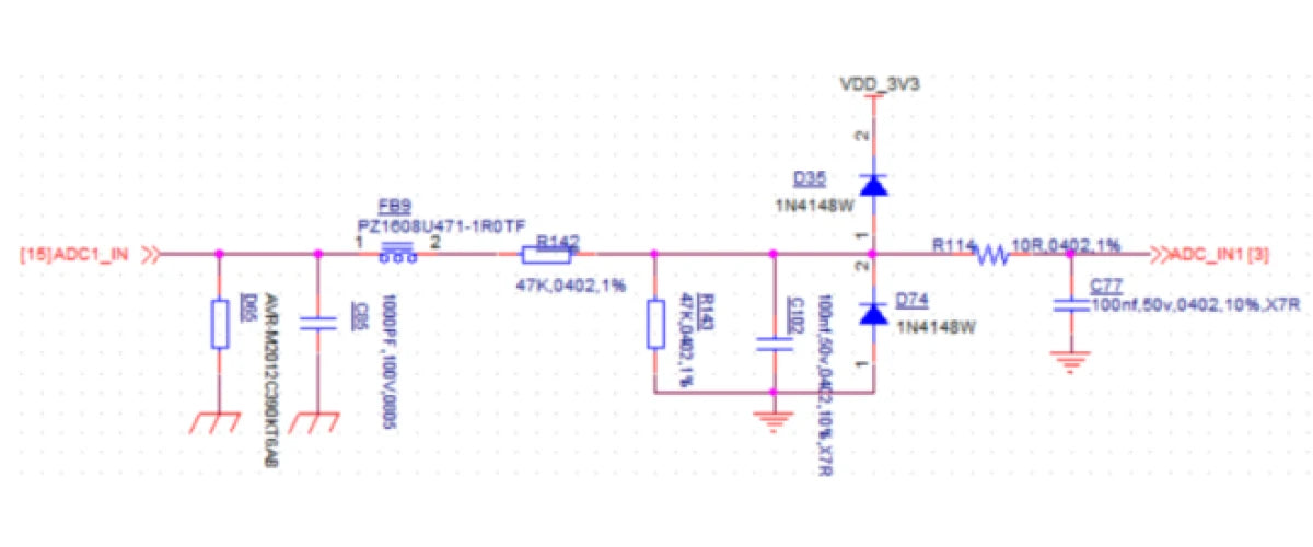
⑦ Voltage clamp
In some ADC detection circuits, two diodes are used for clamping protection. 0.7V is the conduction voltage drop of D1 and D2. When the voltage from Vin is greater than or equal to 3.3V+0.7V, D35 is turned on and Vout will be clamped at 4V; when Vin is less than or equal to -0.7V, Vout will be clamped at about -0.7V.
⑧ Envelope detection
The circuit structure is as follows. The key point of the design is that the time constant of the RC needs to be much larger than the period of the carrier frequency, but also much smaller than the period of the modulation signal.
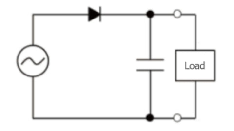
3. MOSFET in inverter
As shown in the circuit above, in a full-bridge inverter, ranging from 500w inverter to power inverter 3000w or more, a set of 4 MOSFETs are connected to the output load. The diagonally connected MOSFETs are alternately switched by an external oscillator, and the input DC from the battery is converted to AC for the load.
The load pass takes the form of a transformer with the low voltage primary coil connected to a MOSFET bridge to achieve the desired DC to AC inversion. H-bridge based on 4 N-channel MOSFET is used in full-bridge inverter, that is, 4 N-channel inverter relies on dedicated driver IC, but has high efficiency and negligible complexity, and is widely used in full-bridge inverter in the vessel.
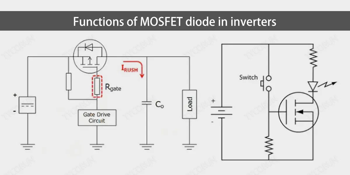
4. Functions of MOSFE diode in inverters
There must be batteries for the inverter, which needs to be charged frequently to keep the inverter continuously outputting and in standby mode. Charging the LFP battery requires a transformer, which must be a high-power device to ensure optimal current flow from the battery.
Using an additional transformer with the inverter transformer is bulky and costly. The MOSFET diode allows the transformer to switch between inverter mode and battery charger mode via a simple relay switching sequence.
5. How MOSFE diode works
As shown in the following circuit: Each MOSFET has an internal MOSFET diode connected across their drain-source pins. The anode of the MOSFET diode is connected to the source, while the cathode pin is connected to the source pin of the device.
Because the MOSFETs are configured in a bridge network, the MOSFET diode are also configured in a basic full-bridge rectifier network format. With a few relays, fast switching is achieved to enable grid AC to charge the off grid solar batteries through the MOSFET diode.
In fact, the MOSFET diode with this bridge rectifier network structure, and the process of using a single transformer as the inverter transformer and charger transformer are relatively simple.
The direction of current flowing through the MOSFET diode is shown in the following circuit:
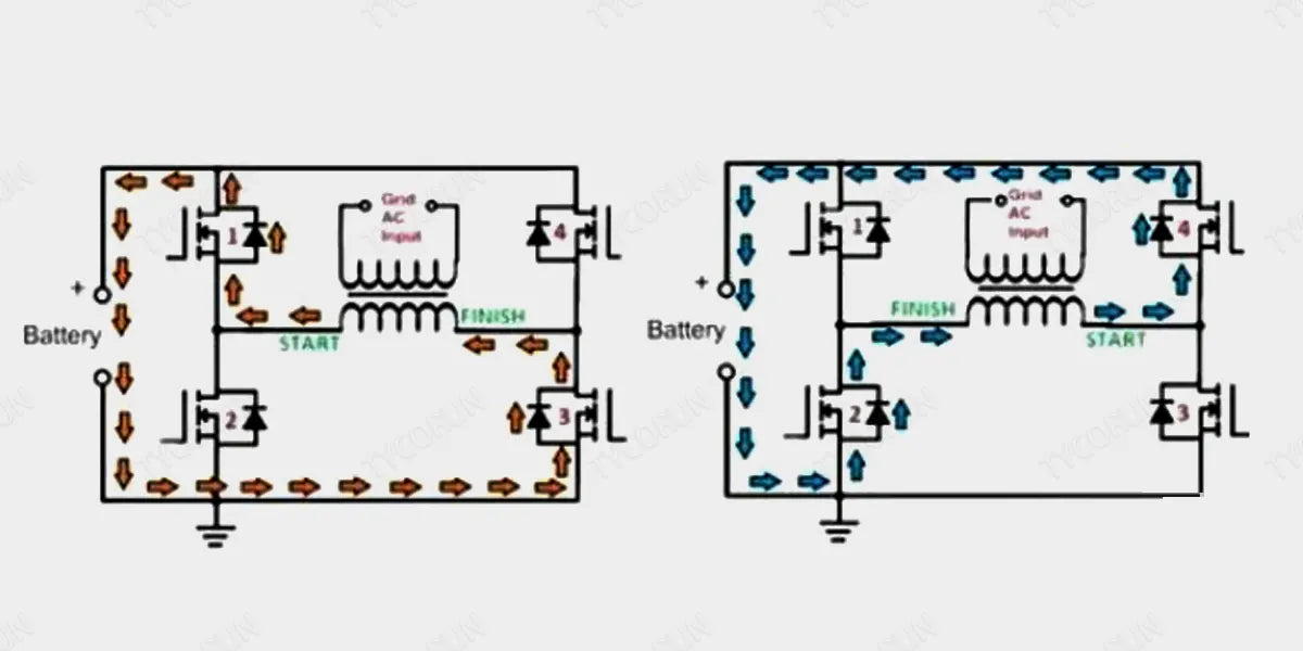
As shown in the figure, if START is positive, the orange arrow indicates the current mode in which the current passes through D1, battery, D3 and flows back to FINISH or the negative terminal of the transformer. On the next AC cycle, the polarity is reversed and the current flows as indicated by the blue arrow through body MOSFET diode D4, battery D2 and back to the FINISH or negative terminal of the transformer winding.
This repeats continuously, converting both AC cycles to DC and charging the battery, such as 12v battery. Because MOSFET diode is included in the system, extreme care must be taken when handling them to ensure that these devices are not damaged during the process.
6. Practical design of MOSFET diode
MOSFET diode is used in the design of rectifiers for charging inverter batteries with relay transfer switches. To ensure that the MOSFET is absolutely safe in charging mode, and when using the MOSFET diode with a transformer AC, the MOSFET diode gate must be kept at ground potential and must be completely disconnected from the power supply DC.
- Connect 1 k resistors between the gate-source pins of all MOSFETs, and connect a cutoff relay in series with the Vcc power line of the driver IC.
- The cutoff relay is a SPDT relay contact with its N/C contact in series with the driver IC power input. In the absence of AC power, the N/C contact remains active, allowing battery power to reach the driver IC, which is MOSFET power supply.
Related posts: 12 volt 12ah lithium deep cycle battery, 12 volt 100ah deep cycle lithium battery, battery stores near me


