Main content:
1. Working principle of double-fed asynchronous generator
As we all know, when the DFIG is running in a steady state, the frequency of its output voltage has a strictly fixed relationship with the number of pole pairs of the generator and the rotational speed of the generator rotor, that is,

In the formula: f is the output voltage frequency of the DFIG, Hz: p is the number of pole pairs of the DFIG; n is the rotational speed of the DFIG, r/min.
Obviously, when the rotor of the doubly-fed asynchronous generator runs at variable speed, the synchronous generator cannot generate constant frequency electric energy. From the structure of the doubly-fed asynchronous generator, the rotor of the wound-rotor doubly-fed asynchronous generator is embedded with three-phase symmetrical windings. According to the principle of the doubly-fed asynchronous generator, it is known that when the three-phase symmetrical alternating current is passed into the three-phase symmetrical winding, a rotating magnetic field will be generated in the air gap of the doubly-fed asynchronous generator. is related to the number of pole pairs of the doubly-fed asynchronous generator, namely

In the formula: n2 is the rotation speed of the rotating magnetic field relative to the rotor itself, r/min; The number of pole pairs of the wire-rotor doubly-fed asynchronous generator; f2 is the three-phase symmetrical alternating current frequency of the three-phase winding of the wound-rotor doubly-fed asynchronous generator rotor, Hz.
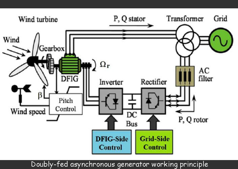
It can be seen from the above formula that changing the frequency f2 of the doubly-fed asynchronous generator can change n2, and if the phase sequence of the three-phase current passing through the rotor is changed, the direction of the rotating magnetic field of the rotor of the doubly-fed asynchronous generator can also be changed. Therefore, if n1 is set to correspond to the grid frequency as
At 50 Hz (f1=50 Hz), the synchronous speed of the DFIG asynchronous generator, and n is the rotation speed of the DFIG rotor itself, as long as n+n2=n1=constant, see the following formula, the DFIG The induced potential of the stator winding of the asynchronous generator, as in the synchronous generator, will always maintain the frequency f1 unchanged.

Then the frequency of the current passing through the three-phase windings of the rotor of the doubly-fed asynchronous generator should be

The above formula shows that when the rotor of the doubly-fed asynchronous generator rotates at a changing speed, as long as the current of the slip rate (that is, f1S) is passed through the three-phase symmetrical windings of the doubly-fed asynchronous generator rotor, then the DFIG will generate A constant frequency potential of 50 Hz can be generated in the stator windings of the machine.
According to the change of the rotor speed of the DFIG, the DFIG can have the following three operating states:
(1) The subsynchronous operation state of the doubly-fed asynchronous generator. In this state, n<n1, the rotating magnetic field rotation speed n2 generated by the current with slip ratio / is the same as the rotation speed of the rotor, so there is n+n2=n1.
(2) The super-synchronous running state of the double-fed asynchronous generator. In this state, n>n1, changing the current phase sequence with the frequency f2 passing into the rotor winding, the rotation of the rotating magnetic field speed n2 generated by it is opposite to that of the rotor, so there is n-n2=n1. In order to realize the reverse direction of n2 steering, the three-phase winding of the rotor must be able to automatically change its phase sequence when the DFIG sub-synchronous operation turns to the DFIG super-synchronous operation; vice versa.
(3) The synchronous operation state of the doubly-fed asynchronous generator, in this state, n=n1 slip rate f2=0, which indicates that the frequency of the current passing through the rotor winding is 0 at this time, that is, the DC current, so it is different from the ordinary synchronous motor. Same.
2. Equivalent circuit and vector diagram of DFIG
According to the motor theory, the equivalent circuit of the doubly-fed asynchronous generator is shown in the figure below.

3. Power transfer relationship of doubly-fed asynchronous generator
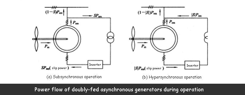
The power of the DFIG in subsynchronous operation and supersynchronous operation is shown in the figure below. In the figure, P is the electromagnetic power of the DFIG, and S is the slip of the DFIG.
