

Main content:
1.Calculate the capacity of the supercapacitor bank with energy as the selection basis
For most applications, the capacity of a single supercapacitor cannot meet the energy requirements, so it is necessary to determine the number of devices required by the energy storage requirements.
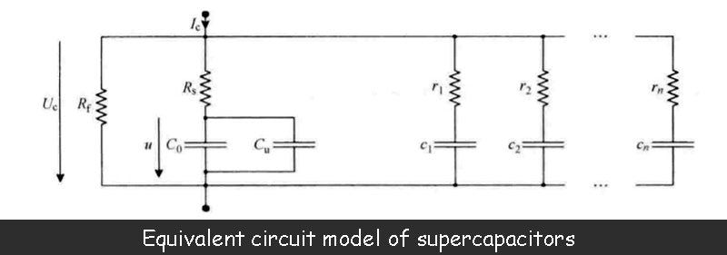
To this end, we first consider the equivalent circuit model shown in the figure above, ignoring the parameters related to the relaxation effect, and only consider the basic capacitance value C of the device C(C=C0). In this case, the maximum energy that the device can store at the maximum allowable voltage UM of the supercapacitor bank capacity is WM, namely

If you want to release all the energy stored in the supercapacitor bank, you need to reduce its voltage from the maximum value UM to 0. However, under a certain power output condition, the current of the supercapacitor bank will tend to infinity as the voltage drops to 0, which will bring great problems in efficiency: because the series equivalent impedance of the energy storage device and the power The conversion device will produce a large loss. In practical applications, in order to improve the system efficiency, it is necessary to limit the variation range of the terminal voltage of the supercapacitor bank within a certain range. A discharge coefficient d is introduced here, which is equal to the minimum allowable terminal voltage of the supercapacitor bank divided by the maximum terminal voltage, and expressed as a percentage.

It can be seen that the total energy WM stored in the capacity of the supercapacitor bank cannot be fully utilized, and only part of the energy can be used, which is called the effective energy Wu.

For example, when d=50% (the minimum voltage is half of the maximum voltage, and the maximum voltage corresponds to a fully charged state), the supercapacitor bank can release 75% of its total energy storage. In order to obtain high efficiency, we generally avoid d below 50% in the application.
From the definition of the effective energy of the supercapacitor bank, the number of devices required to provide energy W can be finally determined, and N is
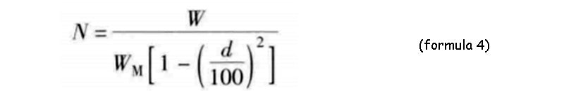
There is no unique solution to the number of devices for a specific supercapacitor bank. The required number depends on the discharge coefficient d of the supercapacitor bank, so there is a great deal of freedom in its capacity design.
2.Calculate the capacity of the supercapacitor bank with power as the selection basis - taking into account the efficiency
As the equivalent circuit model analyzed earlier, the supercapacitor bank contains a series resistance inside, which means that internal losses occur during charging and discharging. If these losses are accounted for, the efficiency of the supercapacitor bank can be obtained, which must be considered when calculating the number of cells in the supercapacitor bank.
For example, the figure below shows the charge and discharge efficiency curves of a supercapacitor bank with parameters of 2600F/2.5V/0.7mΩ under constant current and constant power conditions, respectively. In the figure, the discharge coefficient d is set to 50%. However, even if the charge and discharge current and power are not constant values, you can refer to this curve.
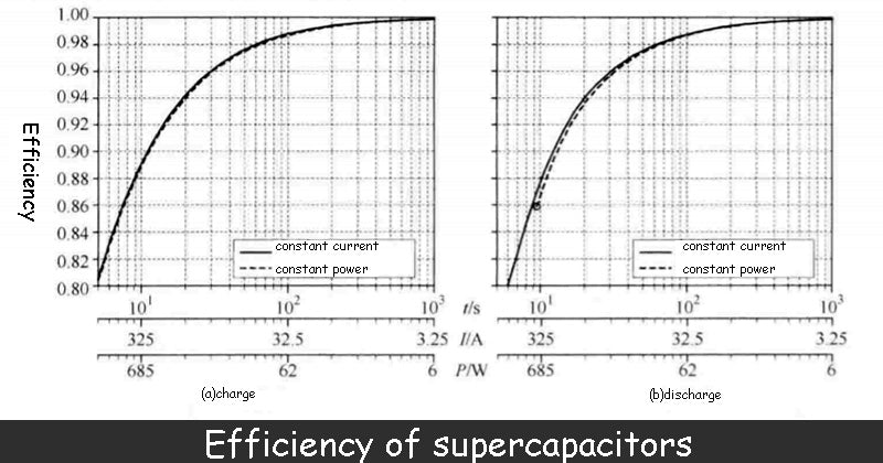
Although the series impedance of the supercapacitor bank is small (0.7mΩ), to achieve efficiency greater than 90%, the current or power must be limited to a certain value when charging, and also when discharging.
That is to say, the current needs to be limited to below 297A during charging, or the power must be limited to below 604W to obtain 90% efficiency. The discharge conditions are more stringent, the current should not exceed 267A, and the power should not exceed 423W.
If we are constrained by the minimum allowable efficiency, the power density of the device of the supercapacitor bank can be calculated, which is obtained by the ratio of the discharge power (423W) to the mass (0.525kg) of the device to ensure that the device obtains 90% efficiency. As a result, the power density of the device in this example is 806W/kg, but the manufacturer's given is 4300W/kg.
It can be seen that the actual performance of the supercapacitor bank device is far from the manufacturer's nominal performance. Therefore, when designing the capacity of the supercapacitor bank, the efficiency problem caused by the internal series impedance of the device must be considered.
The figure below shows a design case of supercapacitor bank capacity considering efficiency. The supercapacitor bank requires 30kW of power to provide 170kJ of energy, and the parameters of a single device are 350F/2.5V/3.2mΩ.
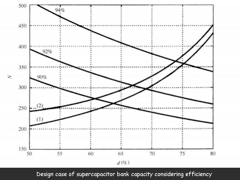
If efficiency is not considered, the number of devices required for the supercapacitor bank can be directly calculated from Equation 4. If the stored energy is known, the number of devices calculated for different discharge coefficients d is not unique. Assuming the value range of the discharge coefficient d is 50%~80%, the curve (1) in the above figure can be obtained, which gives a series of possible choices.
The figure above also shows the selection curve of the number of supercapacitor bank devices at 30kW power and different efficiencies (90%, 92% and 94%). It can be seen from the figure that the efficiency of the supercapacitor bank increases with the number of devices and also increases with the discharge coefficient.
Finally, curve (2) in the figure above presents a range of options for meeting the 170kJ energy storage requirement and considering efficiency. When the efficiency is close to 1 (N is large and d is close to 100%), the curve is close to the ideal curve. In any case, considering the efficiency of the supercapacitor bank leads to an increase in the number of calculated devices, and also limits the variation range of the supercapacitor bank terminal voltage. Ultimately, the number of devices is determined by the intersection of curve (2) (energy with efficiency, selection by) and the equivalent efficiency (power selection by) curve.
In this example, the corresponding design scheme for the energy storage demand of 170kJ/30kW is N=270, d=60.8%, efficiency 90%, or N=365, d=73.8%, efficiency 74%.
Read more: Introduction of battery technology


