

Any two conductors that are insulated from each other and close to each other can form a capacitor. As one of the most widely used electronic components, capacitors have many functions. Among them, filtering is one of the very common functions of capacitors.
Filter capacitor, as an important electronic component, are widely used in automotive electronics, photovoltaic inverters from 500w inverter to 3000w inverter for home solar power system, mobile phones, computers and other products, and they play a role in converting AC and DC power. So do you know what a filter capacitor is? What is the function of filter capacitor? This article will give you a detailed introduction.
Main content:
- How filter capacitor works
- Frequency characteristics of filter capacitor
- Applications of filter capacitor
- Multiple filter capacitors of the same specifications used in parallel
- Multiple filter capacitors of different specifications used in parallel
- Use capacitors to form a low-pass filter
- Port signal bypass capacitor
- Chip power supply decoupling and high-frequency bypass
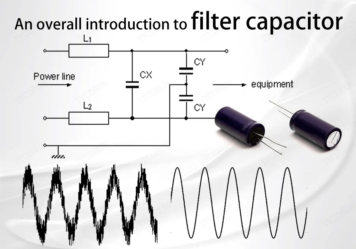
1. How filter capacitor works
A filter capacitor is composed of two electrodes and a dielectric material between them. The medium material is a dielectric. When placed in the charge between two parallel plates with equal and opposite charges, polarization is generated on the surface of the medium. The polarization charge increases the charge bound to the plates and maintains the charge between the plates unchanged.
- The principle of filter capacitor
Filter capacitor has the characteristic of passing high frequencies and resisting low frequencies. Filter capacitor uses this characteristic to provide a low impedance path for interference frequencies. Since the capacitor itself does not consume energy, the interference frequency point only changes the propagation path through the filter capacitor, so the filter capacitor element is also called a reflective filter element.
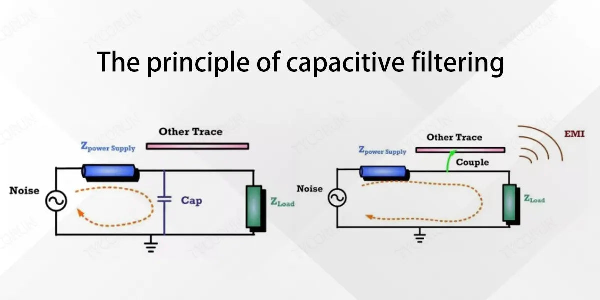
Any signal can only generate current if it forms a loop. The smaller the loop area, the smaller the EMI interference generated. The return area depends on the length of the signal path and the length of the return path.
The smaller the loop area formed by the length of the signal wiring and the length of the return path, the better.Shortening the signal return area by increasing high-frequency capacitance is one of the biggest advantages for solving EMC problems.
In fact, the interference does not pass through the capacitor to the ground and is consumed, but is similar to LFP battery charging. The interference is absorbed to both ends of the filter capacitor. What changes the capacitance value is the speed of charge movement, that is, the speed of charging and discharging. The principle of capacitive bypass is that the interference moves the trajectory repeatedly over a small range of paths.
2. Frequency characteristics of filter capacitor
- Capacitive area and inductive area:
In the low frequency range, it is very close to the ideal capacitor, and the impedance is inversely proportional to the frequency. This region is called the capacitive region. As the frequency changes, the impedance tends to increase, and the influence of the parasitic inductance of the filter capacitor is very obvious. This area is called the inductive area.
- ESR and ESL of filter capacitor:
ESR is the abbreviation of Equivalent Series Resistance,ESL is the abbreviation of Equivalent Series Inductance.
In order to obtain better EMC filtering characteristics, it is very important for the filter capacitor to have low ESR. Due to the resonance point of the filter capacitor itself, when the capacitors are used in parallel, the passband will be broadened and new anti-resonance points will be generated.
In order to reduce the anti-resonance points when selecting filter capacitor to filter out different frequency bands, the best difference between adjacent capacitance values is 100 times.
- Factors affecting filter capacitor ESR/ESL
① The stacked structure of chip capacitors: The more internal electrode layers, the more parallel connections between layers of resistance, that is, the smaller the impedance, and the smaller the ESR for the same reason.
② Resistivity of the material: ESR is related to the resistivity of the material. Different materials have different ESRs. The smaller the ESR, the more noise can be bypassed, that is, the greater the insertion loss, the better the noise suppression capability.
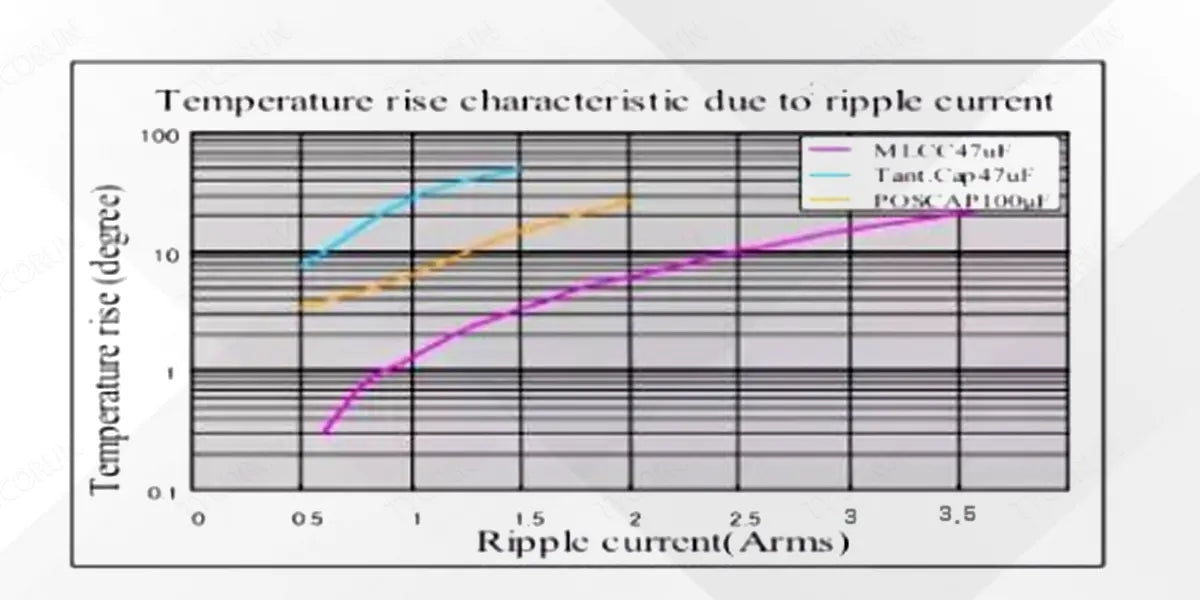
ESR will convert the ripple voltage into heat energy. If the ESR is higher, the more heat energy will be converted. As the ripple voltage increases, the capacitor temperature rises. The larger the ESR, the more the temperature rises. As the temperature rises, the capacitance value will also decrease. Filter capacitor made of different materials have different capacitance value stability as the temperature rises.
3. Applications of filter capacitor
As mentioned above, filter capacitors can be used in various fields such as best solar inverter, off grid batteries system, etc. There are different precautions to be taken when mixing capacitors of the same specification or different specifications, please refer to the following descriptions.
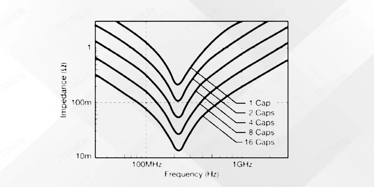
① Multiple filter capacitors of the same specifications used in parallel
If the ripple voltage tolerance of a single filter capacitor is not enough, you can choose to use multiple filter capacitors in parallel. The number of parallel capacitors depends on the ripple voltage requirements. Using multiple capacitors of the same specification in parallel can not only reduce the ripple voltage, but also reduce the ESR , thus increase the insertion loss.
② Multiple filter capacitors of different specifications used in parallel
When the frequency range of noise is very wide and the filtering frequency band of a single capacitor cannot meet the filtering requirements, filter capacitor of different specifications need to be used to widen the passband.
When multiple filter capacitors of different specifications are used, the inductive area and capacitive area of different capacitors will have an intersection point. This intersection point will produce parallel resonance, which will increase the filter impedance and reduce the filtering effect. This intersection point is called anti-resonance.
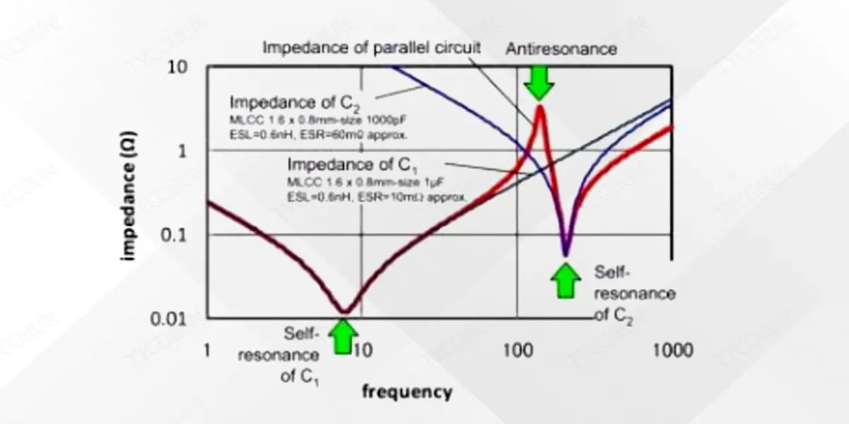
Therefore, when connecting capacitors with different capacitances in parallel, the capacitance difference should be fully considered. It is recommended that the capacitance difference be on the order of 100 times, and the minimum difference is not allowed to be less than 10 times in order to reduce the anti-resonance point filter impedance.
③ Use capacitors to form a low-pass filter
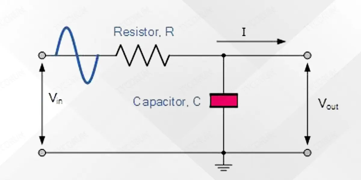
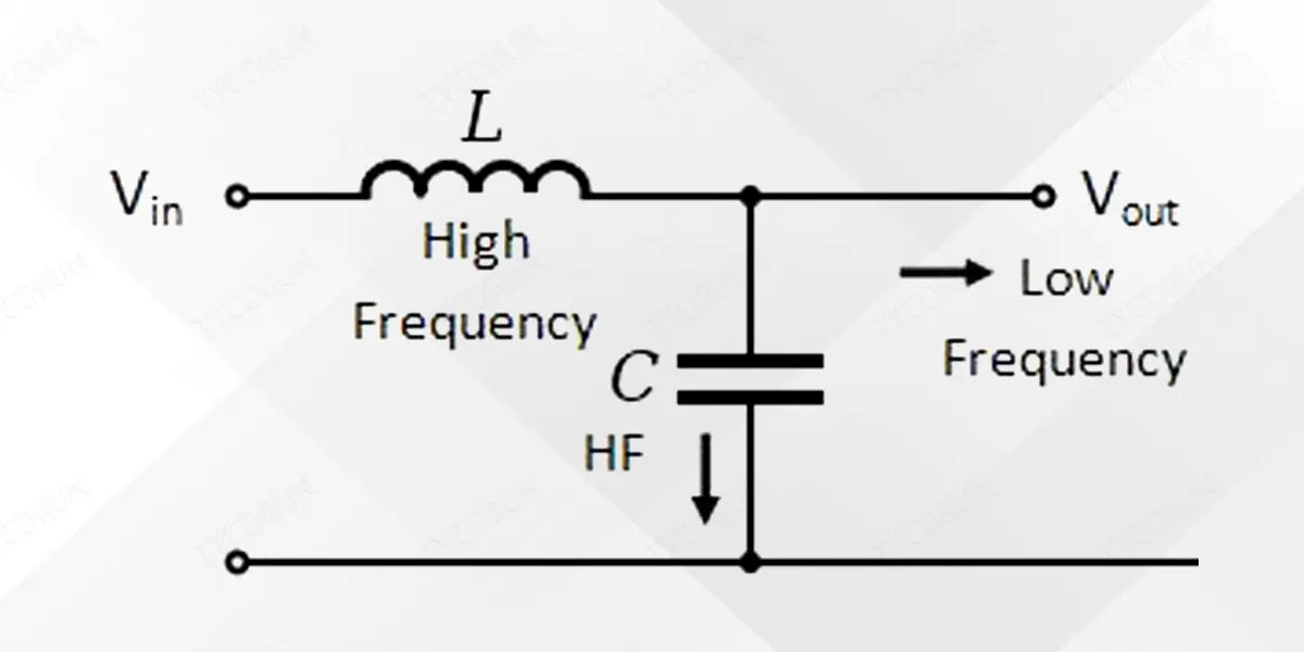
Capacitors usually form a low-pass filter with inductors, magnetic beads, and resistive components to filter out high-frequency noise on signal lines and power lines. When designing low-pass filter parameters, an appropriate circuit structure should be selected based on the signal operating frequency and high-frequency noise frequency.
RC low-pass filter circuit:
LC low-pass filter circuit:
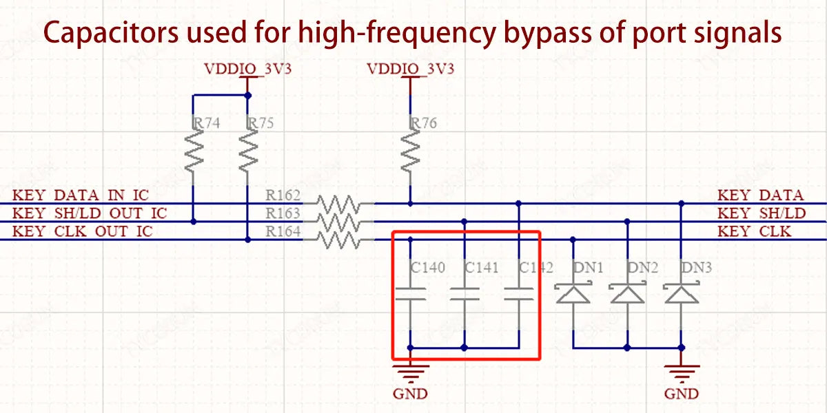
④ Port signal bypass capacitor
In order to prevent the internal interference noise of the PCB from coupling along the connecting cable and causing the antenna to radiate interference outwards, a high-frequency bypass capacitor is usually added to the PCB interface circuit to bypass the intra-board interference back to the source end through the capacitor, while also preventing the interference noise from entering the board and couples to the sensitive signals inside the board.
4. Chip power supply decoupling and high-frequency bypass
- Chip power supply decoupling:
With the continuous improvement of the semiconductor manufacturing process, the chip operating frequency continues to increase, the chip processing data when the rapid switching, sudden changes in current will cause the power supply voltage drop, equivalent to ripple voltage. Increase the decoupling capacitor on the chip power supply pin, quickly compensate for the chip power supply pin due to high-frequency switching caused by the voltage drop, usually using a relatively large capacitor.
- Chip high frequency noise bypass:
Rapid switching when processing data on the chip will generate high-frequency noise interference on the chip's power supply cable, and when high-frequency noise enters different module circuits inside the chip, it will cause mutual interference between module circuits.
The high-frequency current loop formed by high-frequency noise will cause EMI problems if not controlled. In order to cut off the high-frequency noise coupling path, it is necessary to add a high-frequency bypass capacitor to the chip power supply pin to minimize the high-frequency noise. The road area flows back to the source end to improve EMI problems and crosstalk problems between chip modules.
① PCB design for chip decoupling or bypass capacitors
The power supply pin usually places two capacitors or even more during the schematic design stage. When designing PCB Layout, high-frequency filter capacitor should be placed close to the chip pins. Large-capacity capacitors or electrolytic capacitors can be placed slightly farther away from the chip power supply pins.
This is mainly due to the influence of parasitic inductance of high-frequency wiring. When multiple power supply pins are far away from the filter capacitor, different pins will form common impedance coupling because they share a section of PCB wiring.
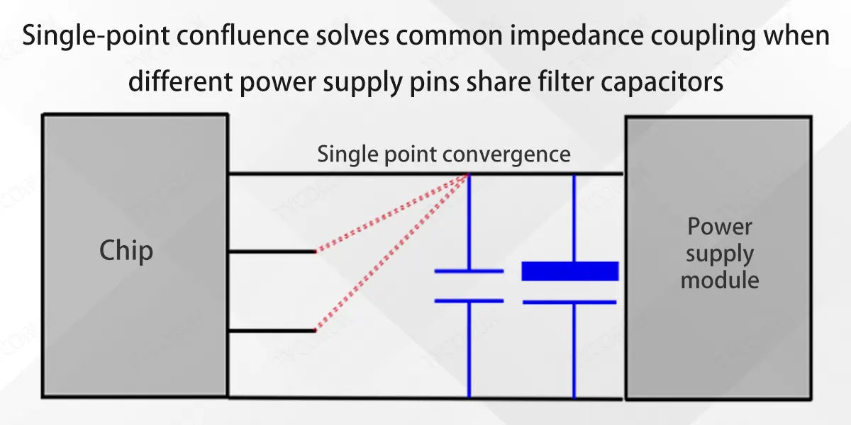
- Single-point busing solves common impedance coupling:
In low-cost design, when the power supply pins of the same voltage chip share filter capacitor, each power supply should be routed at a single point around the filter capacitor to avoid common impedance coupling, as shown in the figure below.
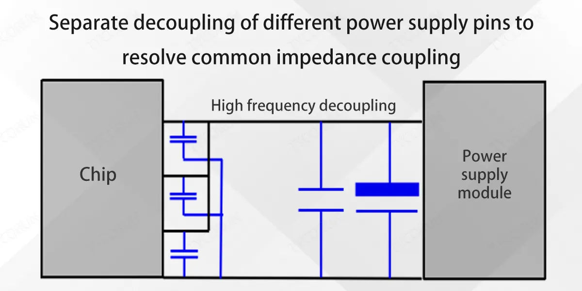
- Separate decoupling of different power supply pins to solve common impedance coupling:
Different power supply pins of the chip use separate high-frequency filter capacitor for high-frequency decoupling, while low-frequency decoupling or filtering can share filter capacitors. This is because of the low-frequency parasitic inductance. The impact is negligible.
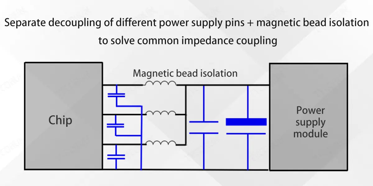
- Separate decoupling of different power supply pins + magnetic bead isolation to solve common impedance coupling:
Limited by the influence of the internal resistance of the power supply pins inside the chip, sometimes when the high-frequency decoupling and bypass effects are not ideal, different methods can be used. The power pins are individually decoupled and magnetic beads are added for high-frequency attenuation isolation to solve the problem of common impedance coupling.
Related posts: coupling capacitor, supercapacitor, top 10 supercapacitor companies


