main content:
The powertrain of a plug-in series hybrid vehicle is shown in Figure 1.
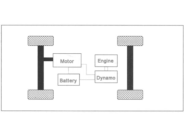
Figure 1 Schematic diagram of the powertrain of a plug-in series hybrid electric vehicle
1. Parameter calculation of drive motor
The drive motor is used as the power source of the series PHEV model, and its parameters determine the maximum speed, grade and acceleration performance of the whole vehicle. Since the existing theoretical calculation methods are relatively mature, the rated power, peak power, rated speed, maximum speed, rated torque and peak torque of the drive motor can be preliminarily calculated with reference to the traditional calculation method, and further analysis and verification are carried out, so that Finally, a drive motor that meets the above requirements is selected.
First, according to the requirements of the maximum speed, calculate the peak power of the drive motor:
P1=νmax/ηT[(m·g·f/3600)+(Cd·A·ν²max/76410)]
In the formula: νmax—maximum speed, km/h;
f—rolling resistance coefficient;
m—mass at half load, kg;
A—windward area, m²;
Cd—air resistance coefficient;
ηT—motor efficiency;
g—gravity acceleration, take 9.8.
According to the requirement of the maximum grade, calculate the peak power of the drive motor:
P2=νC/3600ηT[m·g·sinα+m·g·f·cosα+(Cd·A·ν²C/21.15)]
In the formula: νc——the speed of the climbing vehicle, km/h;
α—Maximum climbing angle, α= arctan(i).
According to the requirements of acceleration performance, calculate the power of the drive motor:
P3=1/3600tm·ηT[δ·m·(ν²m/2√tm)+(m·g·f·νm·tm/1.5)+(Cd·A·ν3m/21.15×2.5)·tm]
Where: νm—acceleration terminal velocity, km/h;
tm—the end time of acceleration, s;
δ——mass conversion factor, take 1.2.
Since the power provided by the drive motor should meet the requirements of the above three aspects, the peak power of the drive motor should be greater than or equal to the maximum value of P1, P2, and P3.
The peak power of the drive motor calculated by the above formula should be greater than or equal to 45.9kW.
In order to meet the power requirements of the whole vehicle, the drive motor is allowed to have a short-term overload during acceleration and climbing. Preliminarily calculate the rated power Pe of the drive motor according to the requirements of the peak power Pmax of the drive motor, and the calculation method is as follows:
Pe=Pmax/λ
In the formula: Pmax—peak power of the drive motor;
λ—The overload multiple of the motor, generally 1.5~2.
Therefore, the rated power of the drive motor is calculated to be 24.75~33kW.
2. Design of powertrain transmission ratio
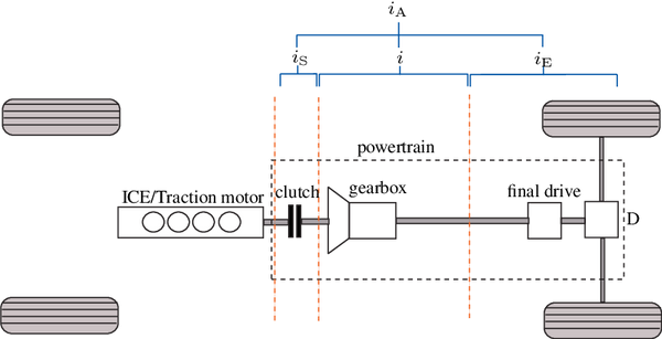
The transmission ratio has an important influence on the power performance of the whole vehicle. Only a reasonable transmission ratio can exert the performance of the drive motor and serve to improve the power performance of the whole vehicle. Since the plug-in series hybrid electric vehicle is only driven by the drive motor, the drive motor has the characteristics of low-speed and high-torque output, and the single-stage transmission ratio can meet the general use requirements.
The transmission ratio is initially determined to meet the following conditions.
(1) The maximum speed of the drive motor must meet the requirements of the maximum vehicle speed. Since the maximum speed of the drive motor is limited, in order to meet the requirements of the maximum vehicle speed, the transmission ratio should not be too large. Calculate the transmission ratio imax using the maximum speed of the drive motor and the maximum speed of the vehicle:
Imax≤(0.377nmax·rwh)/νmax
In the formula: nmax——the maximum speed of the drive motor, r/min;
rwh——the rolling radius of the wheel, m;
νmax——Maximum speed, km/h.
(2) The transmission ratio should ensure that the driving force of the wheels is greater than or equal to the driving resistance, so in order to satisfy the driving of the vehicle, the transmission ratio should not be too small. It can be known from the characteristics of the motor that when the drive motor works at the highest number of revolutions, its torque output value is the smallest. When the whole vehicle is running at high speed, the drive motor outputs a small torque. Therefore, take the torque value at the highest speed of the drive motor to calculate the transmission ratio to make it meet the driving force requirement:
Imin1≥(Fumax·rwh)/(ηT·Tumax)
In the formula: Fumax—the resistance of the road surface when the vehicle travels at high speed on a straight road, N;
Tumax——the maximum torque when the motor outputs at the highest speed, Nm;
rwh——wheel rolling radius, m;
ηT - motor efficiency.
In order to meet the performance index of gradeability, the transmission ratio of the whole vehicle should not be too small. Therefore, the transmission ratio is calculated according to the formula:
Iman2≥[m·g·(f·cosα+sinα)·rwh]/(ηT·Tmax)
Where: Tmax—peak torque of drive motor, Nm.
Calculated imax, = 7.01, imin1 = 3.4, imin2 = 6.69. In order to meet the maximum speed requirements, the vehicle transmission ratio should be less than or equal to imax, in order to meet the driving force and grade requirements, the vehicle transmission ratio should be greater than or equal to imin1 and imin2. Therefore, the transmission ratio range of the whole vehicle is 6.69~7.01, indicating that the single-stage transmission ratio within this range can meet the power requirements of the whole vehicle.
3. Design of battery pack parameters
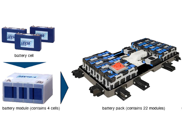
At present, the power batteries used in electric vehicles mainly include lead-acid batteries, nickel-hydrogen batteries and lithium batteries. The output voltage of the battery pack is increased by the single cells in series, and the capacity of the battery pack is increased by the single cells in parallel. Therefore, the output voltage of the battery pack is determined according to the demand of the electric motor, and the capacity of the battery pack is determined according to the driving range requirement of the whole vehicle. Then, the series-parallel mode and number of single cells are calculated according to the voltage and capacity of the battery pack.
The total energy value of the battery pack must meet the requirements of the driving range:
W=(Pv·L)/[(SOC1-SOC0)ηM·ηC·ν]
In the formula: W—the total energy value of the battery pack, kWh;
L - cruising mileage under pure electric conditions, km;
SOC1 - the maximum value within the battery SOC usage range;
SOC0 - the minimum value within the applicable range of battery SOC;
ηM——drive motor efficiency;
ηC——controller efficiency;
Pv——Power at a constant speed of 80km/h, kW.
Considering the service life of the battery and the calculation error, the SOC1 is 100%, and the SOC0 is 30%. ηM·ηC is taken as 0.85. The total energy value of the battery pack is calculated to be 13kWh, and the rated capacity of the battery pack is calculated according to the following formula:
QE≥1000W/U
In the formula: QE——the rated capacity of the battery, Ah;
U——The rated voltage of the battery pack, V.
It is calculated that the rated capacity of the battery pack needs to be greater than 43.3Ah, so a lead-acid battery pack with a rated capacity of 45Ah is selected.
Calculate the number of single cells connected in series according to the rated voltage requirements of the battery pack:
ns=U/u1
In the formula: ns—the number of batteries in series;
u1 - the voltage of the single battery.
ns≥Pemax/(Pbmax·ηM·ηC)
In the formula: Pemax——the peak power of the drive motor, kW;
Pbmax——The maximum discharge power of the single battery, kW.
According to the driving range requirement, calculate the parallel number of single batteries:
np≥QE/Cr
In the formula: nP - the number of parallel batteries;
Cr - the capacity of the single battery, Ah.
4. Parameter matching of engine and generator set
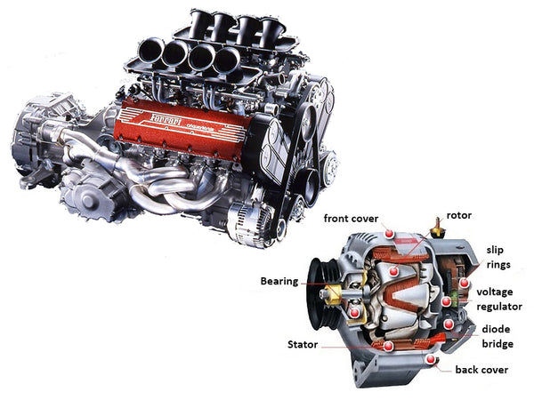
The engine-generator set is a device that provides electric energy for the drive motor and can charge the battery when necessary. Since the energy of the plug-in hybrid vehicle mainly comes from the battery, most of the working conditions are pure electric. Therefore, the matching principle of the engine and the generator set is to meet the requirement of extending the cruising range of the whole vehicle, and it has better economy. Different from traditional fuel vehicles, plug-in series hybrid vehicles will not change the number of revolutions of the engine due to different road conditions, and the engine can work in a more economical area for a long time, so it does not require large displacement and high power. The engine provides a strong power reserve. Under the hybrid power condition, the whole vehicle uses the battery and the engine-generator set as the dual energy sources, and in the hybrid power mode, the main purpose of the whole vehicle is to increase the driving range and ensure the economy. Therefore, the maximum electric power provided by the engine-generator set can be less than or equal to the maximum power of the drive motor, so as to ensure better economy under the hybrid power condition.