


|
main content: |
1. Electric heating

The viscosity of the electrolyte inside the battery increases at low temperature, which hinders the movement of charge carriers, increases the internal resistance of the battery, and even freezes the electrolyte in extreme cases. However, by utilizing the increased resistance of the battery under low temperature conditions, electrical heating can be used to maintain the operating temperature of the battery. Electric heating is a way of heating a battery using the Joule heat generated by passing an electric current through a conductor with a non-zero resistance value. Ahmad et al. compared electric heating with air heating and found that electric heating requires less energy and is more economical.
According to the different power supplies that provide current, it can be divided into internal power heating and external power heating. Wang and JII established three ways of heating with an internal power supply as shown in Figure 1. (a) The battery is heated by the heat generated when the internal resistance of the battery passes current, which is called battery self-heating;
(b) In the mutual pulse heating method, the battery group is divided into two groups m and n. At a certain moment, m is the discharge group, which discharges the charging group n. At the next moment, m is the charging group, which receives the energy released by n for charging. Repeating this, the function of the DCDC converter is to increase the output voltage of the discharge group to a charging voltage suitable for the charging group; the third method, as shown in Figure 1(c), is air convection heating. The results show that the three heating methods have the law that the smaller the discharge voltage, the faster the heating rate and the higher the efficiency. For the mutual pulse heating method, increasing the switching frequency of the charging group and the discharging resistor can effectively prevent lithium ion plating. Among the three heating methods, the mutual pulse heating method has the highest efficiency, and only 5% of the battery capacity is consumed when the battery is heated from -20℃ to 20℃.

According to the classification of current, battery electric heating can be divided into direct current heating and alternating current heating. The high current during the battery charging process and the huge internal resistance under low temperature conditions make the electrolyte excessively vaporized, and the generated gas increases the internal pressure of the battery, which may cause explosion in severe cases. Therefore, DC heating is less practical. In contrast, AC heating can effectively prevent this hidden danger. AC heating is divided into high-frequency AC heating and low-frequency AC heating. Low-frequency AC heating is economical, but the equipment is cumbersome and not suitable for ordinary electric vehicles; the energy required for high-frequency AC heating cannot be provided by batteries, so it can only be used in hybrid vehicles, and the energy is provided by the engine.
Hande et al. performed AC heating on the Japanese Panasonic Ni-MH battery pack with a rated power of 6.5A·h, and the AC frequency was 10~20kHz. In order to ensure that the internal temperature of the battery is equal to the ambient temperature at the beginning of the experiment, the battery was kept at the test temperature for more than 5 hours before the experiment. When the ambient temperature is -20℃ , the resistance of the battery before the convection device is used is 12, and the battery pack SOC = 55%, the temperature change curve of the battery under different AC currents is shown in Figure 2(a). When the alternating current is 60A, the temperature of the battery pack rises to 10℃ after heating for 5 minutes, and the resistance decreases to 0.33Ω at this time. As the current increases, the heating rate increases. When the alternating current is 70A, it takes 3.5 minutes to heat to 10℃ , and when the alternating current is 80A, the battery can be heated from -20℃ to 10℃ in only 2 minutes. When the ambient temperature was lowered to -30℃, the results are shown in Fig. 2(b), and it took 6 min to heat the battery to 10℃ with 60A AC. The SOC of the battery pack is also an important factor affecting the heating rate. Figure 2(c) shows the temperature change curve of the battery under different SOC. It can be seen that with the increase of SOC, the heating rate gradually increases. At SOC of 25%, 55%, and 75%, the cells were heated from -30℃ to 0℃, 10℃, and 15℃ for 6 min, respectively. In addition, the discharge capacity of the battery is also significantly improved after heating with alternating current. Based on the relationship between the battery pack resistance and the internal temperature, Hande also proposed a method to obtain the internal temperature of the battery by measuring the battery pack cells.

Figure 2 - Battery temperature changes under different conditions
In addition, Zhang Chengning et al. used a wide-wire metal film to electrically heat the battery. The wide-wire metal film was plated with a copper film and an insulating wear-resistant layer from an FR-4 sheet, and the battery was heated by copper wire resistance heating. The simulation and experimental results show that the battery can be heated from -40℃ to 0℃ within 1 h using the wide-line metal film. Cosley and Garcial used AC heaters to keep lead-acid batteries from getting too cold. Lefebvre uses a 1kW positive temperature coefficient heating device to heat a pure electric vehicle at an ambient temperature of -5℃, and can heat the battery to 10℃ within 100s.
2. The Peltier effect

Take two different conductors A and B to form a loop, as shown in Figure 3(a), when direct current is applied, the phenomenon of heat absorption or heat release will occur at the connection of the two conductors, forming a high temperature area and a low temperature area. This is the Peltier effect, also known as the second thermoelectric effect. The Peltier effect can be regarded as the reverse effect of the Seebeck effect (the first thermoelectric effect), and the free electrons (charge carriers) that form the current are at different energy levels in different conductor materials, and when it moves from a high energy level to a low energy level, it releases energy to the outside world; on the contrary, when it transfers from a low energy level to a high energy level, it needs to absorb energy, that is, changing the direction of the current can change the direction of heat transfer, as shown in Figure 3(b). The Peltier element is made by using the Peltier effect, which can transfer heat from a low temperature to a high temperature to achieve a heating effect.

igure 3 - Schematic diagram of the Peltier effect
Troxler et al. used a Peltier element (PE) to heat or cool the Li-ion battery to control the temperature distribution of the battery. The heat generated by the Peltier element is carried out by the heat sink radiator, and the coolant used in the heat sink radiator is water. When studying the effect of battery temperature difference on battery resistance, Troxler et al. used the characteristics of PE at one end to absorb heat and one end to release heat to heat and cool the two ends of the battery respectively, so that the temperature at one end of the battery is higher and the temperature at the other end is lower, and the temperature difference between the two ends can reach 40℃.
Alaoui and Salameh designed a battery heating system based on Peltier elements to heat the vehicle battery (front and rear) and the cab, respectively. The heat generated by the Peltier element is transferred to the heat sink radiator, which is then transported by air to the cab, front and rear batteries for heating. The experimental results are shown in Figure 4. When the ambient temperature is 17℃ and the current is 4A, after heating for 20 minutes, the temperature of the rear battery (away from the Peltier heating device) rises to 29℃, while the temperature of the front battery (near the Peltier heating device) rose to 37℃, the consumed battery capacity was 1.5A h, and the COP value of the heating system reached 1.036. When the current increased to 7A, the maximum temperature of the front battery increased to 44℃ under the same conditions, and at this time, the COP value of the heating system decreased to 0.6.
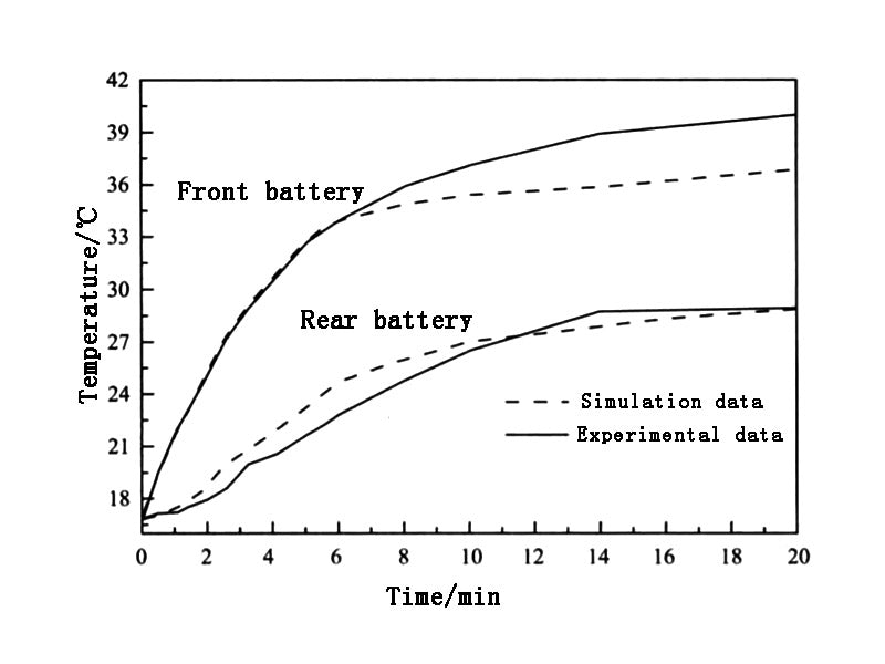
Figure 4 - The temperature change curve of the battery before and after the vehicle


