


1. Electrochemical impedance technology

A small amplitude (several to tens of millivolts) low-frequency sinusoidal voltage is superimposed on the applied DC voltage and applied to the electrolytic cell, and then the AC impedance of the polarized electrode in the electrolytic cell is measured to determine the substance to be measured in the electrolytic cell Electrochemical characteristics, the method is AC impedance method. The AC impedance method mainly measures the Faraday impedance (Z) and the relationship between it and the electrochemical characteristics of the substance to be measured. It is usually measured by the bridge method, which can also be referred to as the bridge method for short.
In this method, the electrochemical process on the polarized electrode is equivalent to an equivalent circuit composed of capacitance and impedance. The AC voltage causes an electrochemical reaction on the electrodes to generate an AC current, and the same AC voltage is added to an equivalent circuit composed of capacitors and resistance elements to generate an AC current of the same magnitude. Therefore, the electrochemical behavior on the electrode is equivalent to the effect of an impedance. Since this impedance comes from the chemical reaction on the electrode, it is called Faraday impedance (Fradic impedance) as shown in Z in Figure 1: CL in Figure 1 represents the capacitance of the electric double layer on the electrode surface, and Ri is the internal resistance of the electrolytic cell. , Rc is the resistance of the polarized electrode itself, and R0 is the resistance in the circuit outside the electrolytic cell. Usually the values of Rc and Ri are small and can be ignored.
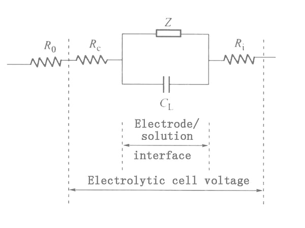
Figure 1 Schematic diagram of equivalent circuit
The Faraday impedance Z itself can be represented by an equivalent circuit. Z can be seen as a resistor Rs and a capacitor Cs in series. This resistance is called polarization resistance, and this capacitor is called pesudo capacitor. The reason why Z is assumed to be formed by the series connection of Rs and Cs is that the impedance is usually measured by an AC bridge. The adjustable components of the AC bridge are variable resistors and capacitors connected in series; Z can also be regarded as a resistance and Capacitors are formed in parallel, but its calculation is much more complicated than that of series circuits. The device for measuring polarization resistance (Rs) and pseudo capacitance (Cs) equivalent to Faraday impedance using an AC bridge is shown in Figure 2. The electrolytic cell CE is connected to the electric bridge circuit as the fourth arm of the electric bridge. The amplitude of the AC voltage supplied by oscillator 0 is about 5mV. The DC voltage P is applied to the two electrodes of the electrolytic cell, Cm and Rm are adjusted to balance the bridge, and the balance point is indicated with an oscilloscope. Find Cm and Rm from the bridge experiment, then use other methods to find the Rc, Ri and CL values in Figure 1, and then use the graph method to find Rs and Cs.
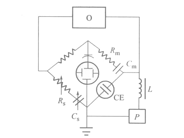
Figure 2 Schematic diagram of AC bridge method
2. Thermodynamic function and battery electromotive force

For reversible batteries, the value of the electromotive force of the battery is related to the change of the free energy of the battery reaction. A chemical reaction that can proceed spontaneously, if the battery is reversibly carried out at an intermediate temperature, the battery can be discharged with an infinitely small current to produce the maximum useful electrical work-W'r (the system is negative for external work). Electric power = voltage power, the voltage under reversible conditions is the battery electromotive force Er; the power can be calculated according to the battery reaction. The electric quantity of 1 mol electron is called 1 Faraday, which is denoted by F. The electric quantity of an electron (e) is 1.6021892×10⁻¹⁹C; therefore:
F=NAe=6.022045×10²³mol-1×1.6021892×10-19C=96487.56C/mol
In general calculations, F=96500C/mol can be taken, and n is the number of charges reacted by the battery, then the amount of electricity passing through the battery is nF, and the maximum electrical work done by the battery-W’r=nFEr. Under isothermal and pressure conditions:
△G=﹣W’r
That is, ΔG=-nFEr.
In the standard state:
ΔGΘ=-nFEΘr
If ΔG and ΔGΘ are known, the values of E and Er can be calculated; conversely, if E and Er are known, the values of ΔG and ΔGΘ can be calculated.


