

There are many research methods for analyzing the thermal behavior and thermal relationship effects of batteries. The most commonly used methods are experimental and numerical simulation methods. The most commonly used numerical simulation methods are computational fluid dynamics (CFD) and finite element method (finite element method). element method, FEM), the mathematical model or numerical model of battery thermal behavior, generally consists of the following three parts: ① energy conservation equation; ② simplified or complex battery heat generation equation; ③ boundary condition equation, including linear/nonlinear , heat conduction / convection heat exchange / radiation heat exchange, etc. At present, many battery thermal models are used to describe the temperature profile or to predict the temperature change with time. Catherino built a thermal mathematical model to study the thermal runaway behavior of lead-acid batteries. Inui et al. Two-dimensional and three-dimensional cylindrical and square Li-ion batteries were obtained, and the temperature distribution inside the batteries was obtained.
There are many mathematical models used to study the thermal behavior of batteries, but the main ones include the following:
(1) Centralized parameter battery thermal model;
(2) Simplified one-dimensional thermal mathematical model;
(3) One-dimensional thermoelectrochemical coupling model;
(4) Two-dimensional transient heat transfer model of cylindrical battery;
(5) Three-dimensional thermal abuse model of Li-ion battery;
(6) Two-dimensional Li-ion battery CFD model.
The lumped parameter battery thermal model was originally proposed by Steve Burch of the US National Renewable Energy Laboratory and improved by Johnson. The heat dissipation of the model is calculated by formula (1)
Qd=(Tb-Tair)/Reff——(1)
In the formula, Reff is the effective thermal resistance, that is
Reff=(1-hA)-(t/kA)——(2)
Among them, h is the surface heat transfer coefficient, which is determined by the temperature of the battery, that is, h=
h={hforced=a[(m/ρA)/5]b, Tb>Tset
{hnature=4, Tb<Tset ——(3)
The air temperature Tair around the battery in formula (1) is
Tair=Tamb+[(0.5Qd)/maircp·air] ——(4)
Al-Hallaj et al. used a simplified one-dimensional lumped parameter thermal mathematical model to simulate the temperature distribution inside a cylindrical lithium battery (Sony, US18650). The energy equation in the mathematical model is
(Ə²T/ər²)+(1/r)(əT/ər)+(q/kcell)=(1/α)(ƏT/Ət)——(5)
In the formula, kcell is the thermal conductivity of the battery; α is the thermal diffusivity; q is the heat source, which is converted from the battery heat production Q, that is
Q=△G+T△S+Wel ——(6)
Q=Q/Vb ——(7)
where S is the entropy. G in formula (6) is Gibbs free energy, Wel is electrical work, which can be obtained from formula (8) and formula (9) respectively
△G=-nFEoc——(8)
Wel=-NFE——(9)
In the formula, n is the number of electrons; F is the Faraday constant; E is the battery voltage; Eoc is the open circuit voltage. The total thermal power Q' of the battery can be expressed as
Q'=I[(Eoc-E)+T(dEoc/dT)]——(10)
A-Hallaj assumes that T=Ta at t=t0, that is, the initial temperature of the battery is equal to the ambient temperature, and the boundary conditions set by Al-Hallaj are
(dT/dr)|r=0 =0
-kcell(dT/dr)|r=R =h(T-Ta) ——(11)
One side is the adiabatic boundary and the other side is the convective heat transfer boundary.
Forgez et al. also used a one-dimensional thermal model to predict the thermal response of LiFePO4/graphite Li-ion batteries. The heat source used was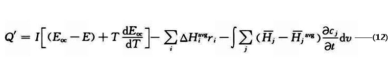
where ΔH is the enthalpy change; ri is the reaction rate; cj is the reaction concentration;-Hj is the local component enthalpy, -Hjavg is the average component enthalpy; the subscript i is the chemical reaction type;
Smith and Wang used a complex one-dimensional lumped-parameter thermoelectrochemical coupled mathematical model to study the pulsating power limit and thermal behavior of a HEV Li-ion battery pack with a voltage of 276 V and a capacity of 6 A·h consisting of 72 cells. , the model is shown in Figure 1. The governing equations used in the model are as follows.
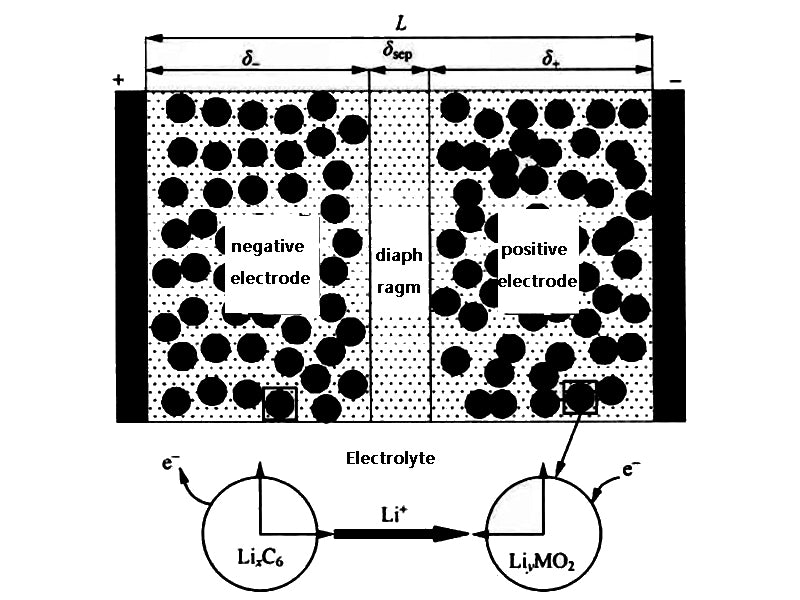
Figure 1 Li-ion battery model
Electrolyte
Əεece/ət=(ə/əx)[Deffe(ə/əx)ce]+[(1-t0+)/F]JLi ——(13)
solid
Əcs/ət=(Ds/r²)(ə/əx)[r²(əcs/ər)]——(14)
Electrolyte (charging)
(Ə/Əx)[keff(Ə/Əx)Фe]+(Ə/Əx)[keffD(Ə/Əx)lnce]+JLi=0——(15)
solid (charged)
(Ə/Əx)[keff(Ə/Əx)Фs]=JLi——(16)
In the formula, ε is the volume fraction; c is the concentration of Li-ion; D is In the formula, ε is the volume fraction; c is the concentration of Li-ion; D is the diffusion coefficient of Li-ion; k is the conductivity of the electrolyte; kD is the diffusion conductivity; t0+ is the number of Li-ion transfer; J is the current density; Ф is the average potential; subscript e represents electrolyte; subscript s represents solid. JLi can be obtained from formula (17)
JLi=asio{exp[(αaF/RT)(η-(RSEI/as)JLi)]-exp[(αcF/RT)(η-(RSEI/as)JLi)]}—(17)
In the formula, io is the current density generated by a single reaction; as is the effective area of the electrode to generate current; αa and αc are the electrochemical reaction conversion coefficients of the positive and negative electrodes, respectively; R is the gas constant; RSEI is the SEI resistance; η is a single electrode The overvoltage of the reaction is obtained from equation (18)
η=Фs-Фe-Eoc——(18)
In the formula, Фs and Фe are the positive and negative electrode potentials of the battery, respectively. Other parameters in equations (8) to (11) are obtained from the following equations
Deffe=Deεpe——(19)
keff=kεpe——(20)
KeffD=(2RTkeff/F)(t0+-1){1+[dln(lnf±)]/dln(lnce)]}——(21)
σeff=εsσ——(22)
σs=3εs/rs=3(1-εe-εp-εf)/rs——(23)
Wu et al. used a two-dimensional unsteady heat transfer model of a cylindrical battery to simulate the temperature distribution inside the Li-ion battery. The radial thermal conductivity kr of the battery model is not equal to the axial thermal conductivity kz, and its energy equation is the same as equation (4) In contrast, considering the anisotropy of thermal conductivity, it is
ρCp(əT/ət)=kr(1/r)(ə/r)(rəT/ər)+kz(ə²T/əz²)+q——(24)
Wu et al. analyzed the effects of natural convection cooling, forced convection cooling and heat pipe cooling by comparing the results of numerical simulation with experiments. The boundary conditions used were as follows:
{əT/ər=0,r=0,0<z<Z
{-kr(əT/əz)=hr(T-T∞), r=R, 0<z<Z
{kz(əT/əz)=hz(T-T∞), z=0, 0<r<R
{-kz(əT/əz)=hz(T-T∞), z=Z, 0<r<R——(25)
The fin boundary conditions are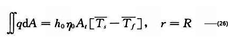
The initial moment T=T∞, t=0, 0<r<R, 0<z<Z. Figure 2 shows the variation of battery temperature with SOC under different discharge currents simulated by the two-dimensional unsteady model
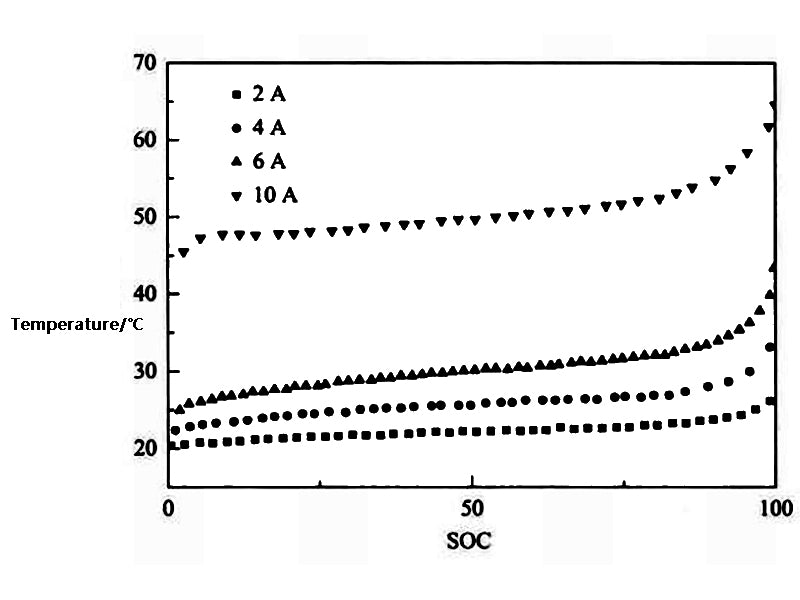
Figure 2 Variation of battery temperature with SOC under different discharge currents
Kim et al. constructed a 3D model of thermal abuse for Li-ion batteries. The heat source of the model is
q=qabuse+qjoul+qcombustion+… -- (27)
In the formula, qjoul and qcombustion represent Joule heat and reaction heat, respectively; qabuse is the additional heat generation after heat abuse, which is calculated by formula (27)
qabuse=qsei+qne+qpe+qele+qnb——(28)
In the formula, qsei is the heat generated by the SEI decomposition reaction; qne is the heat generated by the reaction between the anode active material and the electrolyte; qpe is the heat generated by the reaction between the cathode active material and the electrolyte; qele is the heat generated by the decomposition reaction of the electrolyte, qnb is the heat generated by the reaction between the positive and negative electrodes, which is calculated by the following formula
qi=HiWiRi,i=sei,ne,pe,ele,nb——(29)
Rsei=Aseiexp[-(Ea,sei)/RT]cmseisei——(30)
Rne = Aneexp[-(tsei/tsei,ref)]cmpe.nnegexp[-(Ea,ne)/RT] -- (31)
Rpe=Apeαmpe.pl(1-α)mpe.p2exp[-(Ea,pe)/RT] -- (32)
Rele=Aeleexp[-(Ea,ele)/RT]cmeleele -- (33)
The model of Kim et al. mainly focuses on the thermal runaway behavior in the case of a sharp increase in battery heat generation, especially the thermochemical reaction mechanism.
Lee et al. used a three-dimensional model to study the influence of operating and environmental conditions on the thermal behavior of the battery pack, and further studied the reliability of the model on a 42V electric vehicle system. The maximum and minimum battery temperatures under different ambient temperatures and cycle times are shown in the table. 1 shown.

Table 1 Maximum temperature and minimum temperature of battery under different ambient temperature and cycle times
Kim et al. established a two-dimensional CFD model for a square lithium polymer battery with a capacity of 10A·h, where the current density J was obtained from the formula (34) established by Newman and Tiedemann
J=Y(Vp-Vn-U)——(34)
In the formula, Vp and Vn are the positive and negative electrode potentials of the battery, respectively; Y and U are the parameters obtained by fitting, and the fitting formula was established by Gu et al.
U=a0+a1(DOD)+a2(DOD)²+a3(DOD)³——(35)
Y=a4+a5(DOD)+a6(DOD)²——(36)
In the formula, ai (i=0, 1, 2, 3, 4, 5, 6) is the constant obtained from the experiment, DOD (depth of discharge) in the formula (35) and formula (36) is the depth of discharge, which is determined by the formula ( 2-37) obtained.
DOD=∫t0Jdt/QT——(37)
In the formula, QT red is the theoretical capacity per unit area.
The heat produced by the battery is
Q=aJ[Eoc-E-T(dEoc/dT)]+aprpi²p+anrni²n——(38)
In the formula, ap and an are the specific surface areas of the positive and negative electrodes, respectively; ip and in are the current density of the positive and negative electrodes; Eoc is the open circuit voltage; E is the battery voltage: (dEoc/dT) is the entropy change. Assuming that the outside of the battery is dissipated by natural convection, the heat dissipation rate qconv of the battery is
qconv=2h/d(T-Tair)——(39)
Combining equations (4) and (5), the energy conservation equation in the battery model can be obtained
ρCp(əT/ət)=(ə/əx)[kx(əT/əx)]+(ə/əy)[ky(əT/əy)]+q-qconv——(40)
According to the energy conservation equation established by Eq. (40), Kim et al. simulated the thermal behavior of the prismatic battery during the discharge process,the model is shown in Figure 3. The error between the simulation results and the experimental results is small when the discharge rate is low, and gradually increases when the discharge rate increases.
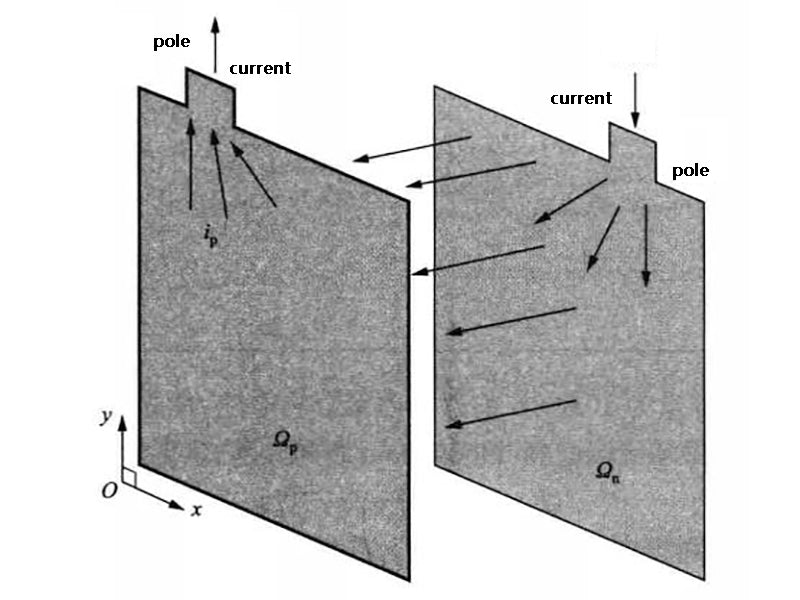
Figure 3 Schematic diagram of the two-dimensional battery heat production model


