

Main content:
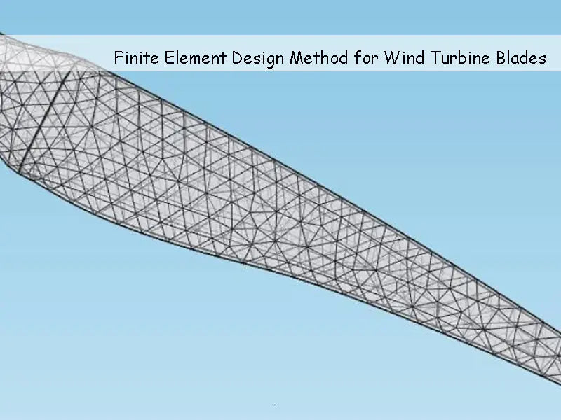
As a mathematical calculation method, the finite element design method has played an increasingly important role in the field of engineering calculation since its inception. Two-dimensional and three-dimensional finite element design methods have been widely used in engineering. This paper focuses on some basic principles and methods of computer-based finite element design analysis.
Many engineering problems can be described by differential equations and corresponding boundary conditions. The definite solution problem composed of differential equations and corresponding boundary conditions is called differential equation boundary value problem. Except for a few simple boundary value problems that can be solved analytically, they can generally only be solved by numerical methods. The finite element design method is a very effective numerical method for solving boundary value problems of differential equations, and it is also one of the core technologies of CAE software.
1. The basic principle and analysis method of finite element design method
The finite element design method is a numerical discretization method, and the numerical solution is carried out according to the variational principle. Therefore, the finite element design method is suitable for solving mechanical problems such as structural shape and boundary conditions are relatively complex, and material properties are not uniform. It can solve various boundary value problems in almost all engineering fields, such as elasticity, elastoplasticity and viscoelasticity, fatigue and fracture. Analysis, dynamic response analysis, fluid mechanics, heat transfer, electromagnetic fields, etc.
The basic idea of the finite element design method is to simplify the structure on the basis of the structural analysis and force analysis of the overall structure, and use the discretization method to treat the simplified continuous structure as consisting of many finite sizes, only within each other. A group of finite elements connected at a finite number of nodes; then, from the element analysis, the stiffness equation of each element is first established, and then the balance equations of the overall structure are obtained by combining each element; finally, the boundary conditions are introduced and analyzed. The numerical approximate solution of the problem can be obtained by solving the equilibrium equations
The steps of structural analysis with finite element design method are: discretization processing, unit analysis, overall analysis, and introduction of boundary conditions to solve.
The finite element design method is divided into three categories: displacement method, force method and hybrid method. The displacement method is easy to realize computer automatic calculation.
2. Discretization in Finite Element Design Analysis
Since the actual mechanical structure is often complex, even if the structure is simplified, it is still difficult to describe with a single unit. Therefore, in the finite element design and analysis of the mechanical structure, it is necessary to select appropriate elements and carry out reasonable collocation to discretize the continuous structure, so that the established computational mechanics model can be as close as possible to the actual structure in the engineering sense and improve the calculation accuracy. The main problems to be solved in the structure discretization process are: element type selection, element division, element numbering and node numbering.
2.1 Principles of unit type selection
In the finite element design analysis, the correct selection of element types plays an important role in the correctness of the analysis results and the calculation accuracy. The selection of unit types should generally follow the following guidelines.
(1) The selected element type should have a good degree of proximity to the geometry of the structure.
(2) To truly reflect the working state of the analysis object, for example, when the large machine tool foundation is subjected to force, the bending deformation is very small and can be ignored. In this case, the plane stress element should be used.
(3) According to the requirements of calculation accuracy and considering the size of the calculation workload, linear or high-order units are appropriately selected.
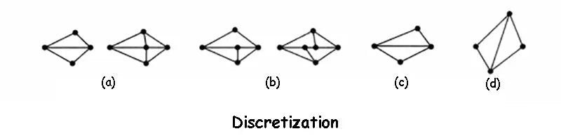
3. Discretization
After the element type selection is completed, the analytical model can be discretized and divided into finite elements. Elements are connected only at nodes, and loads are transferred between elements only through nodes.
When performing discretization processing, the number of units should be determined according to the required calculation accuracy and computer hardware performance. At the same time, attention should also be paid to the following issues: ① The vertex of any unit must be the vertex of the adjacent unit at the same time, but not the interior point of the adjacent unit. In the image below, (a) is correct and (b) is incorrect. ②As far as possible, the length of each side of the unit should not differ too much. It is better not to have obtuse angles in triangular elements, (c) correct, (d) incorrect. ③ Different parts of the structure should be divided into units of different sizes. The important parts have dense meshes and small cells, and the secondary parts have sparse meshes and large cells. ④ For components with different thicknesses or a combination of several materials, the thickness mutation line or the boundary line of different materials must be taken as the boundary line of the unit, that is, the same unit can only contain one thickness or one material constant. ⑤ If the member is subjected to concentrated load or sudden change of distributed load, the part affected by concentrated load or the part of sudden change of distributed load should be divided into smaller parts, and nodes should be set at the point of concentrated load or the sudden change of load. ⑥ If the structure and load are symmetrical, only a part can be taken for analysis to reduce the amount of calculation.
4. Finite element design analysis
The purpose of element analysis is to establish the finite element design balance equation of the element by analyzing the physical characteristics of the element.
4.1 Finite element design displacement interpolation function
After the discretization of the structure is completed, the characteristics of the elements can be analyzed. In order to express the displacement, strain and stress in the element by the nodal displacement, when analyzing the problem of the continuum, it is necessary to make certain assumptions about the displacement distribution in the element, that is, it is assumed that the displacement is a simple function of the coordinates. This function is called the displacement interpolation function of the element, or displacement function for short.
Choosing an appropriate displacement interpolation function is the key to finite element design analysis. The displacement function should be as close to the actual displacement as possible to ensure that the calculation results converge to the exact solution. The displacement function must meet three conditions: ① The displacement function must be continuous within the unit, and the displacements between adjacent units must be coordinated. ②The displacement function must include the rigid body displacement of the element. ③ The displacement function must include the constant strain state of the element.
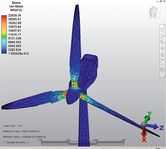
5. Post-processing of finite element design
The post-processing of the finite element design mainly summarizes the analysis results of the finite element design, and conducts visual processing, extracts the results that the designer cares about most from the analysis data, and checks and checks the rationality of the product design. Post-processing mainly includes: sorting the stress and displacement, finding the extreme value, checking whether the stress and displacement exceed the limit value or specified value; displaying the stress distribution of elements and nodes; simulating the structural deformation process with animation; Color cloud map or contour, isosurface, section plane, vector diagram, draw stress-strain landline, etc.
Read more: Conceptual Design of Wind Turbine Prototype


