Main content:
- Fully matched system for charging control
- Parallel regulator for charging control
- Part parallel regulator for charging control
- Series regulator for charging control
- Zener diode regulator for charging control
- Secondary Square Array Switching Regulator for Charging Control
- PWM switch for charging control
- Pulse charging with charging control
Battery charging control is usually accomplished by controlling voltage or controlling current. Generally speaking, there are three battery charging methods: constant current charging, constant voltage charging and constant power charging, and each method has different voltage and current charging characteristics.
In the photovoltaic power generation system, the charging control controller is generally used to control the charging conditions and protect the overcharge. The most commonly used charge controllers are: fully matched systems, parallel regulators, partial well-connected regulators, series regulators, zener diode secondary square array switching regulators, pulse width modulation, and pulse charging circuits. Different charging control circuits can be selected for different photovoltaic power generation systems. The main factors to be considered are to be as reliable as possible, high control accuracy and low cost. The switching device used can be a relay or a MOS transistor. However, the use of pulse width modulation type controllers often includes the tracking function of the maximum power, and only MOS transistors can be used as switching devices. In addition, the charging control process of the battery is often realized by controlling the terminal voltage of the battery, so the charging control in the photovoltaic power generation system is also called a voltage regulator. Several types of charging control systems are introduced in detail below.
1. Fully matched system for charging control
A perfectly matched system is a system of series diodes. This diode is usually a silicon PN junction or a Schottky diode to prevent the battery from discharging to the photovoltaic array during periods of low solar radiation.
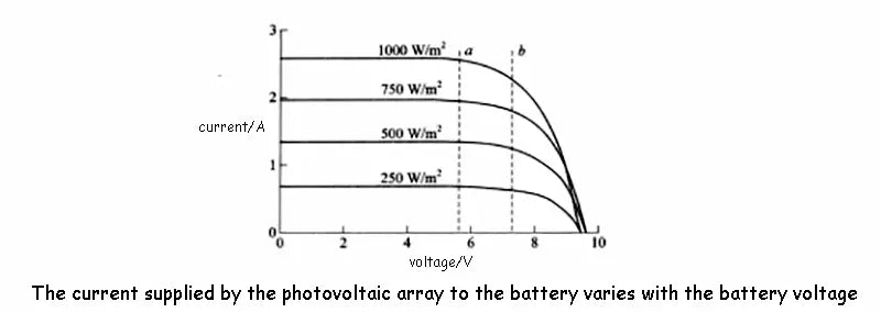
The battery charging voltage is increased while the battery is receiving charge. As shown in the figure below, the operating point of the photovoltaic square array moves from point a to point b as the current decreases.
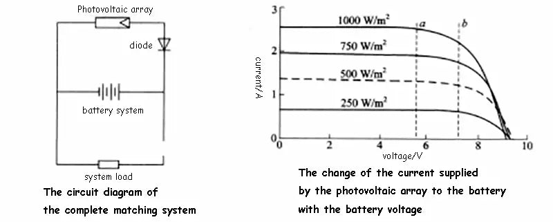
The operating voltage range between point a and point b must be selected first to ensure the best match between the photovoltaic array and the battery. The problem with this charging control system is that the photovoltaic array will work under changing solar radiation conditions. is uncertain. With this system design, the battery can only be fully charged when the sun's irradiance is high, and the efficiency of the phalanx will be reduced when the sun's irradiance is low.
2. Parallel regulator for charging control
The shunt regulator is currently the most common charge control circuit used in photovoltaic power generation systems. Typically a shunt regulator is used to keep the charge current constant.
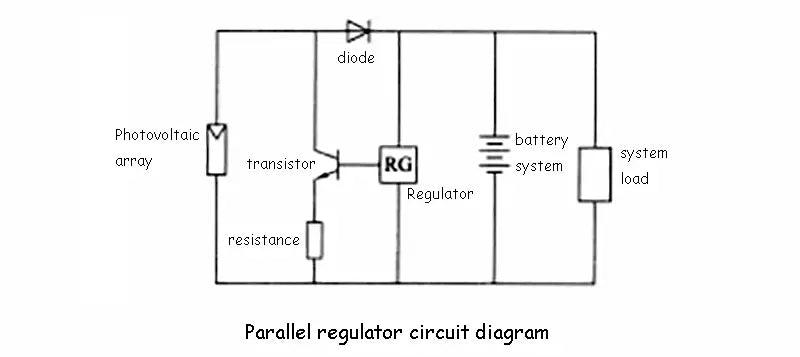
The regulator regulates the charging of the battery based on voltage, current and temperature. It realizes overcharge protection by connecting the transistor to the parallel circuit of the battery through a parallel resistor. Usually the regulator uses a fixed voltage threshold to control the on or off of the quality tube switch.
The electrical energy shunted in parallel can be used to power the auxiliary load to make full use of the output electrical energy of the photovoltaic array.
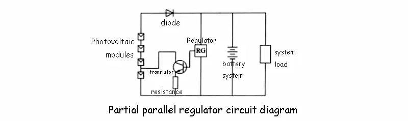
3. Part parallel regulator for charging control
The purpose of using a partial parallel regulator is to reduce the voltage of the photovoltaic array, thereby achieving a two-stage voltage characteristic. The advantage of the shunt regulator is to reduce the open-circuit voltage of the transistor, but its disadvantage is that it requires additional line connections, so it is generally rarely used.
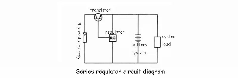
4. Series regulator for charging control
In a series regulator, the voltage across the battery is constant, and its current varies with the series regulator. This quality tube regulator is usually a two-stage regulator. A series transistor replaces the required series diode.
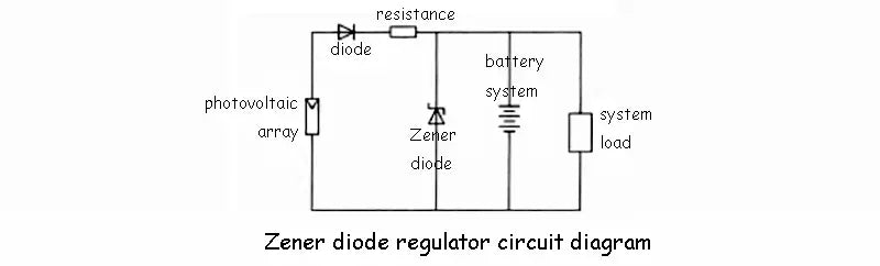
5. Zener diode regulator for charging control
Zener diode regulators use a Zener diode voltage stabilizer. This kind of charging control system is very simple, but it has the disadvantage that the series resistance consumes power, so it has not been widely used.
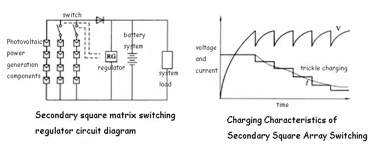
6. Secondary Square Array Switching Regulator for Charging Control
The charge control circuit of the secondary square matrix switching regulator. When the battery voltage reaches a certain predetermined value, the components of the photovoltaic array or some rows of components will be disconnected. The figure below shows the relationship between its charging voltage and current. The main problem with secondary phalanx switching regulators is the complexity of the switching arrangement. This regulator is mostly used in large photovoltaic power generation systems to provide a quasi-conical charging current.
7. PWM switch for charging control
The pulse width modulation switch is used in the charging control circuit of DC-DC conversion. Its circuit is shown in Figure 9-9. Due to the complexity and high cost of this modulation switch, it is difficult to be widely used in small photovoltaic power generation systems.
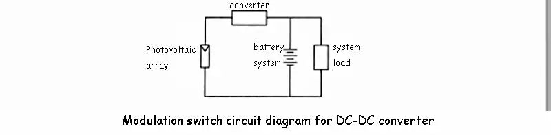
In any case, the principle of DC-DC conversion using pulse width modulation presents many attractive features, especially in large systems. These features include:
(1) The photovoltaic array voltage output to the DC-DC converter can vary with the possible use of increased or decreased converters. This is especially useful in those places where the photovoltaic array and the battery are separated by a large distance. The PV array voltage can be raised or lowered to the battery voltage at a central point to reduce power losses in the cables.
(2) It can provide good charging control characteristics to the battery.
(3) The maximum power point that can be used to track the photovoltaic array.
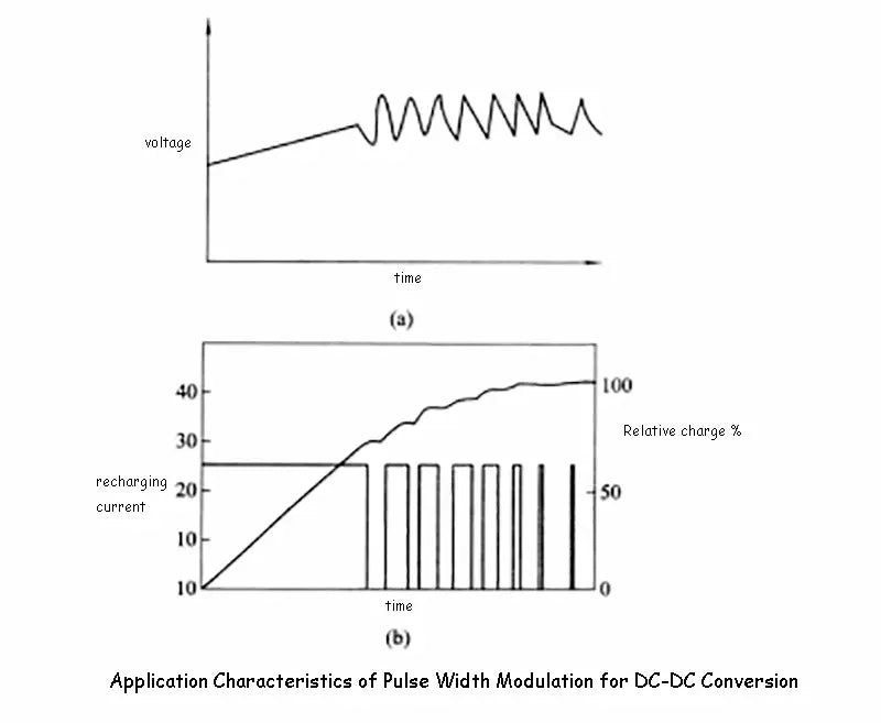
Such DC-DC converters are commonly used in large-scale photovoltaic power generation systems, however, they offset many of their advantages with a low efficiency of 90% to 95%. Using pulse width modulation, the output of the DC-DC converter can be varied by charging as shown in Figure 9-10.
The pulse width of the current will decrease as the voltage increases until the average current decreases towards zero. This method is now more commonly used because it replaces relays with solid-state switching devices, which can achieve a higher switching frequency range.
8. Pulse charging with charging control
Pulse charging, like pulse width modulation, is now increasingly common due to its low-cost solid-state switching technology. The battery is charged with constant current to bring its voltage to a higher threshold. Then, the regulator turns off until its voltage drops to a reduced threshold. These two thresholds are chosen to ensure that the battery can operate at high voltage with lower input current when the battery reaches a fully charged condition.
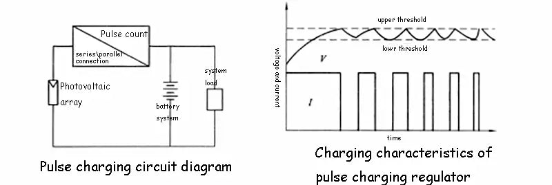
Typical hysteresis is 50mV per cell, so a lead-acid battery cycle is about 2.45V-2.50V. For this system to work well, these thresholds should be reached at least once a month and not more than once a week.
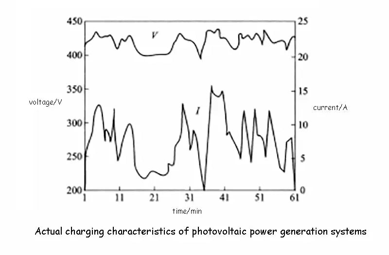
Incorporating a true voltage limiter is essential when using pulse charging control circuits. Because the voltage limiter can prevent excessive switching of the relay, this phenomenon will exist for a long time when the battery voltage greatly exceeds its design limit. In the various charging curves presented here, except for the perfectly matched system, the working voltage of the battery is limited to the interval a and b of the curve shown in the figure below. Based on this assumption, the flowing current should be close to the short-circuit current Is.
The sun is assumed to be in a state of continuous high radiation intensity. In an actual photovoltaic power generation system covered by changing cloud cover, usually the actual charging curve varies greatly, as shown in the figure below. In the photovoltaic power generation system in the state of low cloud cover, the solar radiation curve can be considered as a sinusoidal curve.