Main content:
1. The geometry and aerodynamic properties of the blade airfoil
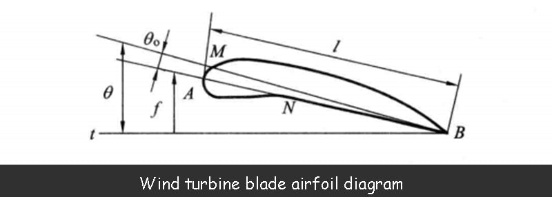
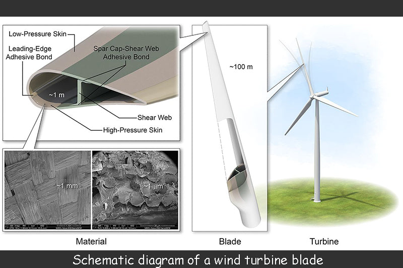
Equation 1-1 below is a schematic diagram of a wind turbine blade. The function of the blades is to convert wind energy into mechanical energy. In aerodynamic, the rotor of a wind turbine is generally composed of 2 to 3 blades. Consider first the case of a stationary airfoil being blown by the wind. According to aerodynamic, the velocity of the wind is the vector ν, oriented parallel to the plane of the airfoil. The aerodynamic knowledge about the definition of airfoil geometry is as follows: the pointed tail point B of the airfoil is called the trailing edge, and the point A on the round head is the leading edge. The length of the straight line AB connecting the front and rear edges is l, which is called the chord. AMB is called the airfoil upper surface and ANB is called the airfoil lower surface. The curved dashed line from the leading edge to the trailing edge is called the midline of the airfoil. The elevation angle θ is the angle between the chord and the airflow velocity vector ν.

In aerodynamic, what are the definitions related to the wind wheel:
(1) Wind wheel shaft: the axis of the rotary motion of the wind wheel.
(2) Rotation plane: perpendicular to the shaft of the wind wheel, the plane of the blade when rotating.
(3) Diameter of the wind rotor: the diameter of the swept surface of the wind rotor.
(4) Blade axis: the longitudinal axis of the blade, around which the deflection angle (installation angle) of the blade relative to the rotation plane can be changed,
(5) Blade section: the section of the blade at the radius r that intersects the cylinder with the rotor shaft as the axis.
(6) Installation angle or pitch angle: the angle α between the chord line of the airfoil and the rotating surface at the radius r is shown in Figure 3-6.
In aerodynamic, R is the radius of the rotor, which can also be called the length of the blade: consider the blade as an ellipse, and r is the semi-major axis of the blade, which is usually called the blade radius here; α is the chord and rotation of the outer airfoil of the blade radius The included angle of the angular surface; t is the maximum width of the blade; V is the airflow velocity at the outer edge of the blade.
2. Design the main components of the wind turbine according to the aerodynamic
According to aerodynamic, after years of development, wind turbines now have many forms, some are old wind turbines, which are no longer used; some are modern wind turbines, which are being widely used by people; some are under research. Although wind turbines come in different forms, they all work on the same principle, all based on aerodynamic, using the rotor to absorb energy from the wind and then convert it into other forms of energy.
The following mainly studies the wind rotor, tower and air-to-wind device of the new type of wind turbine.
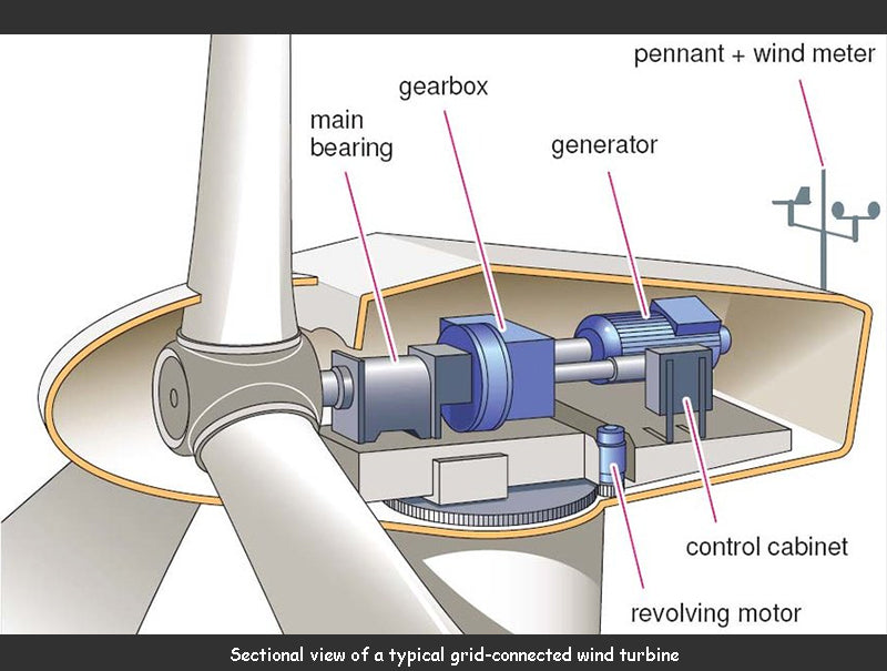
In aerodynamic, a wind turbine is mainly composed of a wind wheel, a tower and a wind counter.
2.1 Aerodynamic knowledge of wind turbine
The wind wheel of the horizontal axis wind turbine in aerodynamic consists of 1 to 3 blades. Blades are the parts of a wind turbine that absorb energy from the wind. There are four forms of leaf structure.
(1) Solid woody leaves. This blade is carefully machined from high-quality wood, and its surface can be covered with a layer of fiberglass to prevent rain and dust from eroding the wood.
(2) Use the tube as the force beam of the blade, use the foam material, balsa wood or other material as the intermediate filler, and coat the surface with a layer of glass fiber reinforced plastic.
(3) The blade is composed of tube beam, metal rib and skin. The metal skin is made into an aerodynamic shape, and the skin, ribs and tube beams are glued together with steel nails and epoxy.
(4) The blade is made of tube beam and glass fiber reinforced plastic skin with aerodynamic shape. The FRP skin is thick and has a certain strength, and at the same time, some foam ribs can be bonded in the FRP skin.
According to aerodynamic, when the wind wheel rotates, the blades are affected by centrifugal force and aerodynamic force. The centrifugal force is a pulling force on the blades in aerodynamic, and the aerodynamic force makes the blades bend. When the wind speed is higher than the design wind speed of the wind turbine, in order to prevent the damage of the blades, the wind rotor needs to be controlled. According to aerodynamic, there are three main ways to control the wind rotor: ① Make the wind rotor deviate from the main wind direction; ② Change the blade angle (change the pitch angle); ③ Use the spoiler to generate resistance to reduce the speed of the wind rotor.
According to aerodynamic, when the wind speed is too high, the wind rotor will deflect to the side or upward, thereby reducing the windward side of the wind rotor and preventing the rated speed from exceeding. The side deflection wind rotor has an eccentric distance between the center of the wind rotor and the rotation center of the wind turbine support tower. When the wind speed is too high, the rotating surface of the wind rotor is deflected to the side. For the upward deflection wind rotor, when the wind speed is too high , the rotating surface of the rotor is deflected upward.
For the aerodynamic principle of small wind turbines, when the speed of the blades exceeds the rated speed, the centrifugal force of the control hammer connected to each blade increases the pitch angle of the blades, thereby avoiding the effect of wind. The aerodynamic principle of the machine is used to control the output power by changing the pitch of the control system.
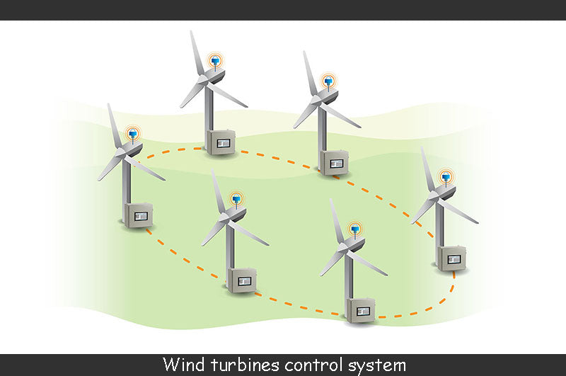
The control system of the wind turbine is shown in the figure below. According to the aerodynamic, after the turbulence controller is installed on the tip of the wind turbine blade, the centrifugal force increases at the over-speed, and the turbulence controller overcomes the tension of the spring to open, Increased resistance, thereby reducing rotor speed. On large wind turbines, in order to completely stop the rotor, a mechanical brake can be installed on the low-speed shaft or the high-speed shaft.
2.2 Aerodynamic knowledge of the tower
In order to make the wind rotor run at a higher wind speed on the ground, the wind rotor needs to be supported by a tower. At this time, the tower is mainly subjected to two forces: one is the gravity of the wind turbine, which presses down on the tower; the other is the resistance, which bends the tower to the downstream direction of the wind. There are two basic forms of the tower, the tensioning support type and the cantilever dyeing type. The tower can be a cylindrical structure made of wooden rods and iron pipes, or a truss structure made of steel.
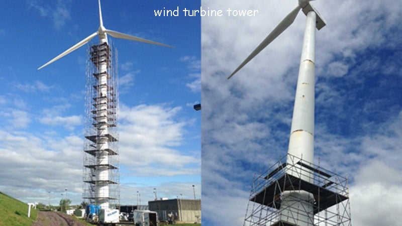
The construction of the tower is costed according to the principles of aerodynamic. According to aerodynamic, the force that destroys the tower is mainly the gravity of the wind turbine and the resistance of the tower. Therefore, the selection of the tower should be determined according to the actual situation of the wind turbine. The towers of large wind turbines are basically conical cylindrical steel towers.
2.3 Aerodynamic knowledge of wind installations
The wind in nature often changes in both speed and direction. For horizontal-axis wind turbines, in order to obtain the highest wind energy utilization efficiency, the rotating surface of the wind rotor should always be aligned with the wind direction. For this reason, a wind counter is required.


